8
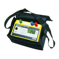
Digital Ground Resistance Tester Model 3640 and 4610
2.3 Fault Indicator LEDs
The three indicators described below conrm the correct measurement
beingtakenifnoneofthemarelit.
2.3.1 X-Z Fault
ThisLEDsignalsthatvoltagebetweenterminalsXandZexceeds30Vpeak.
Therearefourpossiblecauses:
• theresistanceofthecurrentcircuitbetweenXandZistoohigh
• interferencevoltageinthecurrentcircuitistoohigh
• thefuseisblown
• thecircuitisopen(leadnotconnected)
2.3.2
X-Y High Resistance (3640) - Xv-Y High Resistance (4610)
ThisLEDsignalsthattheresistanceinthevoltagecircuit(betweenXvand
YorXandY)istoohigh(approx50kΩ)orthatthecircuitmaybeopen.
• Flashing willcontinue throughout the measurement, evenif the
resistancedropsbelowthethreshold(e.g.afterreconnectingor
loweringauxiliaryrodresistance).
• Inthiscase,you mustreleasethepush-buttonandpressagain
afterthefaulthasbeencorrected.
• Occasionally, a stray voltage above 6VDC may also set off this
light.
• Checktheleadsforapossiblesolution.
2.3.3 X-Y High Noise (3640) - Xv-Y High Noise (4610)
ThisLEDsignalsthepresenceofexcessivenoise(approx13Vpeak)in
thevoltagecircuit(betweenXvandYorXandY).
• Oneremedyistouseshieldedleadsfromtheinstrumenttothe
auxiliaryelectrodes.
• Connectalltheshieldstotherodundertest.

 Loading...