Digital Ground Resistance Tester Model 3640 and 4610
33
4.9 Soil Resistivity Measurements (Model 4610 Only)
Why make soil resistivity measurements?
Soilresistivitymeasurementshaveathreefoldpurpose.First,suchdata
areusedtomakesub-surfacegeophysicalsurveysasanaidinidentifying
orelocations,depthtobedrockandothergeologicalphenomena.Second,
resistivityhasadirectimpactonthedegreeofcorrosioninunderground
pipelines.Adecreaseinresistivityrelatestoanincreaseincorrosiveactiv-
ityandthereforedictatestheprotectivetreatmenttobeused.Third,soil
resistivitydirectlyaffectsthedesignofagroundingsystem,anditistothat
taskthatthisdiscussionisdirected.Whendesigninganextensiveground-
ing system,it isadvisable to locate the areaof lowestsoil resistivity in
ordertoachievethemosteconomicalgroundinginstallation.
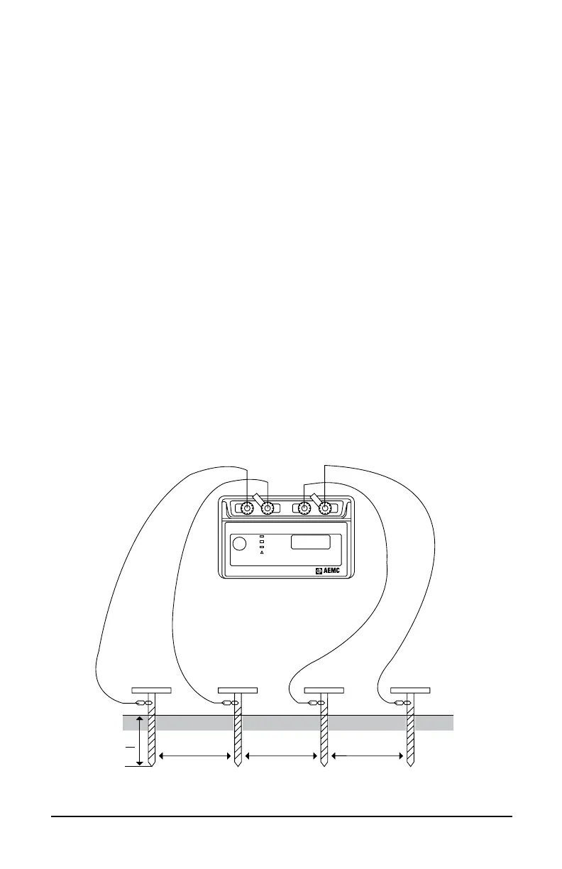
Resistivitymeasurementsareoftwotypes,thetwopointandthefourpoint
method.Thetwopointmethodissimplytheresistancemeasuredbetween
twopoints.For mostapplications,themostaccuratemethodisthefour
point method, which is used by the AEMC
®
Instruments Model 4610
GroundTester.Thefourpointmethod,asthenameimplies,requiresthe
insertionoffourequallyspaced,andin-line,electrodesintothetestarea.
Aknowncurrentfromaconstantcurrentgeneratorispassedbetweenthe
outermostelectrodes.Thepotentialdrop(afunctionoftheresistance)is
thenmeasuredacrossthetwoinnermostelectrodes.TheModel4610is
calibratedtoreaddirectlyinohms.
b<
a
20
aaa
Z electrodeY electrodeXv electrodeX electrode
Ω
Press To
Measure
X-Z
Xv-Y
Xv-Y
ZYXXv
C1 P1 P2 C2
Fault
Hi Resistance
Hi Noise
GROUND RESISTANCE TESTER
MODEL 4610
AUTORANGING
REFER TO USER MANUAL
FOR FAULT WARNING LIGHT
EXPLANATIONS
!
®
INSTRUMENTS
225
Figure 20