Digital Ground Resistance Tester Model 3640 and 4610
25
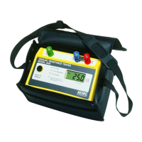
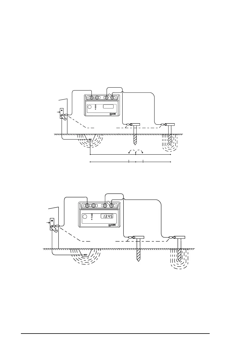
4.4 Measuring Resistance of Ground Electrodes
(62% Method)
The62%methodhasbeenadoptedaftergraphicalconsiderationandafter
actualtest.Itisthemostaccuratemethodbutislimitedbythefactthat
thegroundtestedisasingleunit.Thismethodappliesonlywhenallthree
electrodesareinastraightlineandthegroundisasingleelectrode,pipe,
orplate,etc.,asinFigures11and12.
Model 3640
Alligator Clips
YZX
52% 62%
72%
0%
100% of distance
between X and Z
Ground Rod Y Electrode Z Electrode
Ground Rod
Y Electrode
Z Electrode
Ground
Strip
-10% 3rd
Measurement
+10% 2nd
Measurement
Ω
Press To
Measure
X-Z
Xv-Y
Xv-Y
ZYXXv
C1 P1 P2 C2
Fault
Hi Resistance
Hi Noise
GROUND RESISTANCE TESTER
MODEL 4610
AUTORANGING
REFER TO USER MANUAL
FOR FAULT WARNING LIGHT
EXPLANATIONS
!
®
INSTRUMENTS
46.9
Figure 11
Model 4610
Ω
Press To
Measure
X-Z
Xv-Y
Xv-Y
Fault
Hi Resistance
Hi Noise
AUTORANGING
REFER TO USER MANUAL
FOR FAULT WARNING LIGHT
EXPLANATIONS
!
®
INSTRUMENTS
Alligator Clips
Ground Rod
Y Electrode
Z Electrode
Ground
Strip
GROUND RESISTANCE TESTER
MODEL 4610
ZYXXv
C1 P1 P2 C2
Figure 12
ConsiderFigure13,whichshowstheeffectiveresistanceareas(concentric
shells)ofthegroundelectrodeXandoftheauxiliarycurrentelectrodeZ.
Theresistanceareasoverlap.Ifreadingsweretakenbymovingtheauxiliary
potentialelectrodeYtowardseitherXorZ,thereadingdifferentialswould
be great and one could not obtain a reading within a reasonable band
oftolerance.Thesensitiveareasoverlapandactconstantlytoincrease
resistanceasYismovedawayfromX.