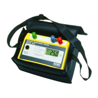
Digital Ground Resistance Tester Model 3640 and 4610
9
2.4 Over-range Indication
Over-rangeisindicatedwhenthedisplayreads1,orwhenthedisplayis
blinkingandtheindicatorislit.
2.5 Fault LED Indication – Tips and Solutions
TheLEDindicatorsshowexcessive electrode resistance andexcessive
transientnoiseand/orstraycurrent.
Intheeventofanincorrectmeasurementindication:
• Improvethequalityoftheconnectiontoearthofauxiliaryground
electrodesYandZ.Zisthemostlikelysourceofproblemscaused
byexcessiveelectroderesistance.
• Checkconnectionsforcontinuitybetweenleadsandelectrodes.
• Be sure that electrodes are properly inserted; they should be
buriedasmuchaspossible.
• Ifhighelectroderesistancestillexistsafterproperlyinsertingaux-
iliaryelectrodesintotheearth,trypouringwateronandaround
theauxiliaryelectrodes.Thiswillimprovetheirelectricalconnec-
tiontoearth.
• Ifstraycurrentsaresuspected,onesolutiontoreducetheirinu-
enceistomovebothYandZelectrodesinanarcrelativetotheX
electrode(try,e.g.,a90°shift),andtestagain.
• Displayof0.00:XvandYareshort-circuited.
• Displayof<0:XandZorXvandYrodsarereversed.
NOTE: Accuracy may be affected by auxiliary ground rod (Ry, Rz) resistance
levels and by stray signal levels (earth currents).