24
Digital Ground Resistance Tester Model 3640 and 4610
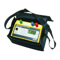
4.3.1 Position of the Auxiliary Electrodes in Measurements
Thegoalinpreciselymeasuringtheresistancetogroundistoplacethe
auxiliarycurrentelectrodeZfarenoughfromthegroundelectrodeunder
testsothattheauxiliarypotentialelectrodeYwillbeoutsideoftheeffec-
tiveresistanceareasofboththegroundelectrodeandtheauxiliarycurrent
electrode.ThebestwaytondoutiftheauxiliarypotentialrodYisoutside
theeffectiveresistanceareasistomoveitbetweenXandZandtotake
areadingateachlocation.IftheauxiliarypotentialrodYisinaneffective
resistancearea(orinbothiftheyoverlap),bydisplacingit,thereadings
takenwillvarynoticeablyinvalue.Undertheseconditions,noexactvalue
fortheresistancetogroundmaybedetermined.
X-Y Distance
Resistance
Reading Variation
Effective Resistance
Areas (Overlapping)
XY'YY''Z
Figure 9
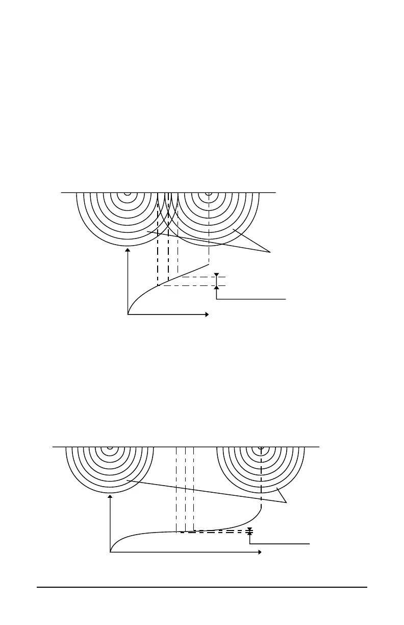
On the other hand, if the auxiliary potential rod Y is located outside of
theeffectiveresistanceareas,asYismovedbackandforththereading
variationisminimal.Thereadingstakenshouldberelativelyclosetoeach
other,andarethebestvaluesfortheresistancetogroundofthegroundX.
Thereadingsshouldbeplottedtoensurethattheylieina“plateau”region
asshowninFigure10.
X-Y Distance
Resistance
Reading Variation
Effective Resistance
Areas (No Overlap)
XYYY'' Z
Figure 10