DC Voltage Measurements
OBSERVE ALL SAFETY PRECAUTIONS AND WARNINGS
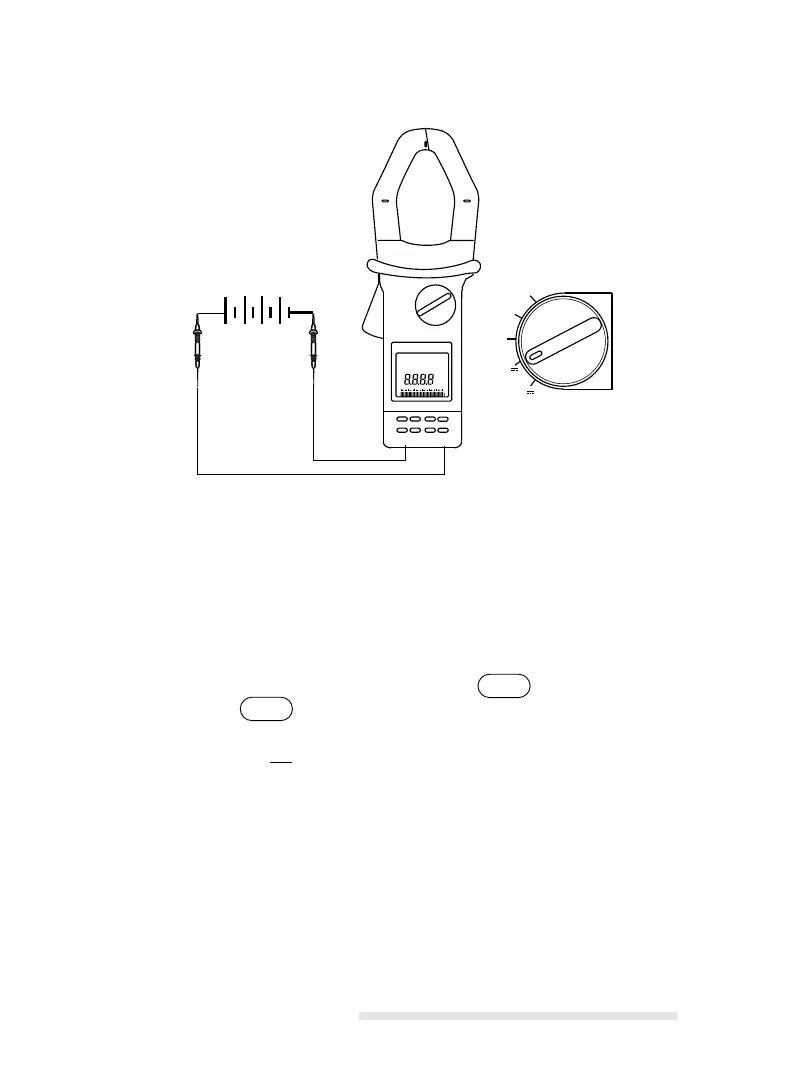
Operating Procedure
1) The voltage input connectors are color-coded 4 mm banana jacks
located on the base of the instrument. When making voltage connec-
tions, be sure to observe the proper polarity and connection integrity.
Select the appropriate lead termination (test probe or clips) for the
application. Insert the RED test lead into the jack and the BLACK
test lead into the jack.
2) Turn on the instrument using the rotary selector to the voltage mea-
surement function V . Selection is confirmed with a short beep when
exiting OFF.
3) Touch or connect the voltage test leads to the circuit under test.
4) Take a reading from the display. Voltage measurements are possible
from 50 mV to 600 V DC.
- - -