24
10 SUMMARY MENU
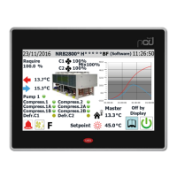
The SUMMARY menu provides a simplied representation of the unit with a selec-
tion of the operating parameters (in real time), on the basis of the feedback from
the various probes installed.
10.1 PAGE RELATING TO THE COOLINGONLY UNITS OR
HEAT PUMP WITH COOLING OPERATION
— Indicates the current outside temperature
— Indicates the current fan speed (sub-divided on the basis of the circuits - C1 for
the rst, C2 for the second)
— Indicates the current power value request from the system to the unit
— Indicates the power percentage supplied by circuit 1 to meet the system request
— Indicates the power percentage supplied by circuit 2 to meet the system request
— Indicates the current situation of the compressors, divided on the basis of the
circuit - those of circuit 1 on the left, those of circuit 2 on the right. (the com-
pressors shown are the ones that are currently active; if no compressor is ON, no
labels will be displayed)
— Indicates the current situation of the pressure values on the unit circuits (AP1
= high pressure ("AP") on circuit 1, AP2 = high pressure on circuit 2, BP1 = low
pressure on circuit 1, BP2 = low pressure on circuit 2)
— Indicates the current operating set-point for the unit
— Indicates the status of the pump (if it's active, the relative label is displayed) and
the temperature of the water entering the heat exchanger
— Indicates the temperature of the water leaving the heat exchanger
10.2 PAGE RELATING TO THE COOLINGONLY UNITS OR
HEAT PUMP WITH HEATING OPERATION
— Indicates the current outside temperature
— Indicates the current fan speed (sub-divided on the basis of the circuits - C1 for
the rst, C2 for the second)
— Indicates the current power value request from the system to the unit
— Indicates the power percentage supplied by circuit 1 to meet the system request
— Indicates the power percentage supplied by circuit 2 to meet the system request
— Indicates the current situation of the compressors, divided on the basis of the
circuit - those of circuit 1 on the left, those of circuit 2 on the right. (the com-
pressors shown are the ones that are currently active; if no compressor is ON, no
labels will be displayed)
— Indicates the current situation of the pressure values on the unit circuits (AP1
= high pressure ("AP") on circuit 1, AP2 = high pressure on circuit 2, BP1 = low
pressure on circuit 1, BP2 = low pressure on circuit 2)
— Indicates the current operating set-point for the unit
— Indicates the status of the pump (if it's active, the relative label is displayed) and
the temperature of the water entering the heat exchanger
— Indicates the temperature of the water leaving the heat exchanger
10.3 PAGE RELATING TO THE UNITS WITH FREECOOLING
1
— Indicates the current outside temperature
— Indicates the current fan speed (sub-divided on the basis of the circuits - C1 for
the rst, C2 for the second)
— Indicates the current power value request from the system to the unit
— Indicates the power percentage supplied by circuit 1 to meet the system request
— Indicates the power percentage supplied by circuit 2 to meet the system request
— Indicates the current situation of the compressors, divided on the basis of the
circuit - those of circuit 1 on the left, those of circuit 2 on the right. (the com-
pressors shown are the ones that are currently active; if no compressor is ON, no
labels will be displayed)
— Indicates the current situation of the pressure values on the unit circuits (AP1
= high pressure ("AP") on circuit 1, AP2 = high pressure on circuit 2, BP1 = low
pressure on circuit 1, BP2 = low pressure on circuit 2)
— Indicates the current operating set-point for the unit
— Indicates the status of the pump (if it's active, the relative label is displayed) and
the temperature of the water entering the heat exchanger
— Indicates the temperature of the water leaving the heat exchanger
— Indicates the current operating set-point in Free-cooling