25
EN
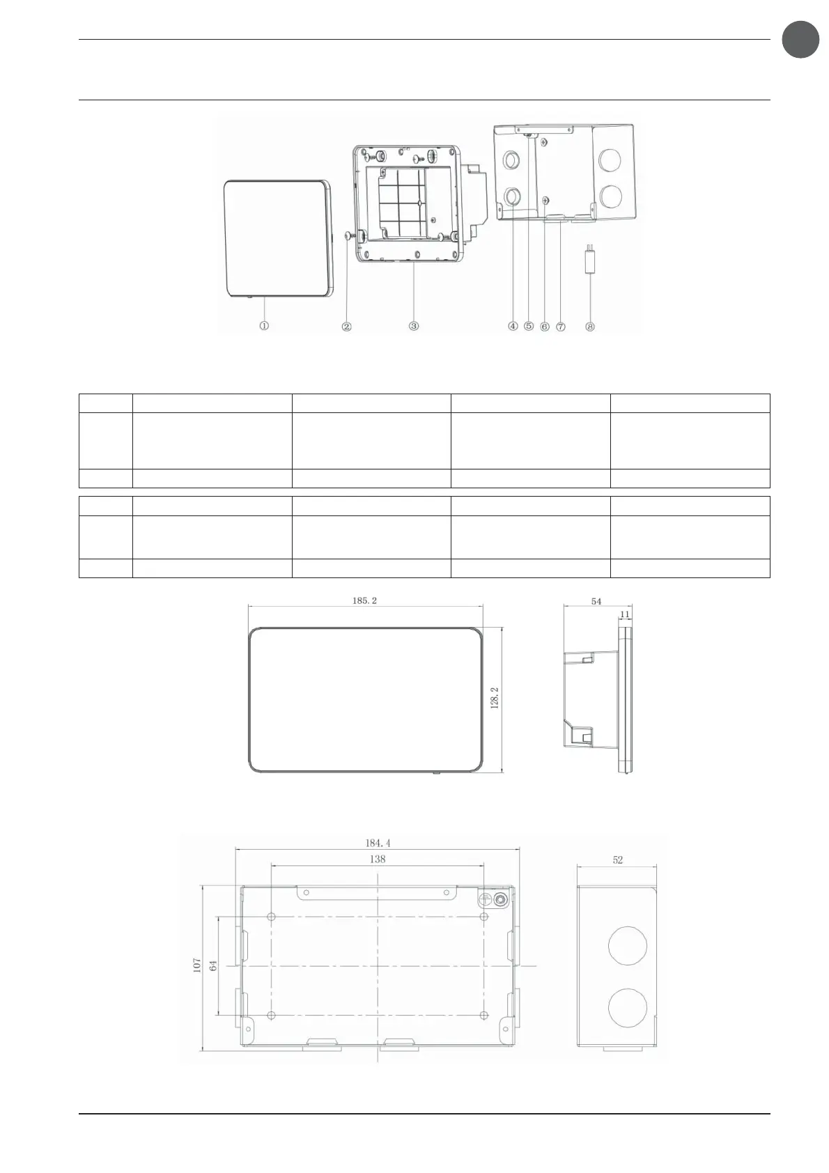
3. INSTALLATION
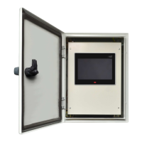
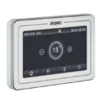
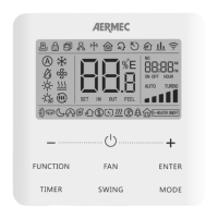
Fig.3.1 Parts of the centralized controller
Fig.3.2 Dimensions of the centralized controller
No.1234
Name Touch screen
Self-tapping screws ST4,2×9,5
MC
(to secure the rear cover of
the controller)
Rear cover of the controller Rubber grommet
QTY1416
No.5678
Name
M4×12 screw
(to fasten the earth cable)
ST4,2×16 FA screw
(to secure the cover of the
electrical box)
Cover of the electrical box Terminating resistor
QTY1411
Fig.3.3 Dimensions of the metal electrical box