IT EN FR DE ES
14 IFCZ-ACTALJ 1807- 4696520_04
The FCZ ACT fan coil with electronic thermostat, tall cabinet for vertical
installation, varnished with corrosionresitant polyester powder, RAL 9003.
The delivery grille is in RAL 7047 and the feet for oor-standing solutions
(ZXZ accessory) are made of plastic and in RAL 7044. The FCZ ACT fan coil
concentrates high technological and functional characteristics that make
it the ideal climate control unit for all types of rooms. The supply of climate
controlled air is immediate and distributed throughout the room; FCZ ACT
generates heat
if included in a heating system with boiler or heat pump but may also be used
in summer as an air conditioner if the heating system has a water chiller.
The response to the commands is immediate if the room temperature and
water in the tank conditions so allows; with some special system settings, the
delay at which the fan comes on after the last command can be
up to a maximum of 2’40”. The removable drip tray and fan volute ensure
thorough cleaning of the unit (by specically trained personnel),
essential for installations in venues subject to crowding or in those with special
hygiene requirements. The quietness of the new centrifugal fan assembly is
such that at normal speed of use you cannot hear when the FCZ ACT cuts in.
The use of the electronic control
panel avoids the annoying noise typical of mechanical thermostats.
The control panel is located under the ap with grille on the right or left side
of the fan coil. The panel can be protected against tampering, by locking
the cover ap with a screw. The control panel with electronic thermostat
controls the operating functions of the fan coil to keep the set temperature
in the room, allows the temperature electronic adjustment, manual and
automatic fan speed change. The heating or cooling functioning mode is
automatically set (season change) and depends on the temperature of the
water circulating in the system. The FCZ ACT fan coil has been designed to
meet all
system requirements thanks to its extensive range of accessories.
Easy installation with reversible hydraulic connections during installation.
Full respect for accident prevention regulations.
Routine maintenance is reduced to periodic air lter cleaning with a vacuum
cleanertemperature of the water circulating in the system.
The FCZ ACT fan coil has been designed to meet all system requirements
thanks to its extensive range of accessories.
Easy installation with reversible hydraulic connections during installation.
Full respect for accident prevention regulations.
Routine maintenance is reduced to periodic air lter cleaning with a vacuum
cleaner.
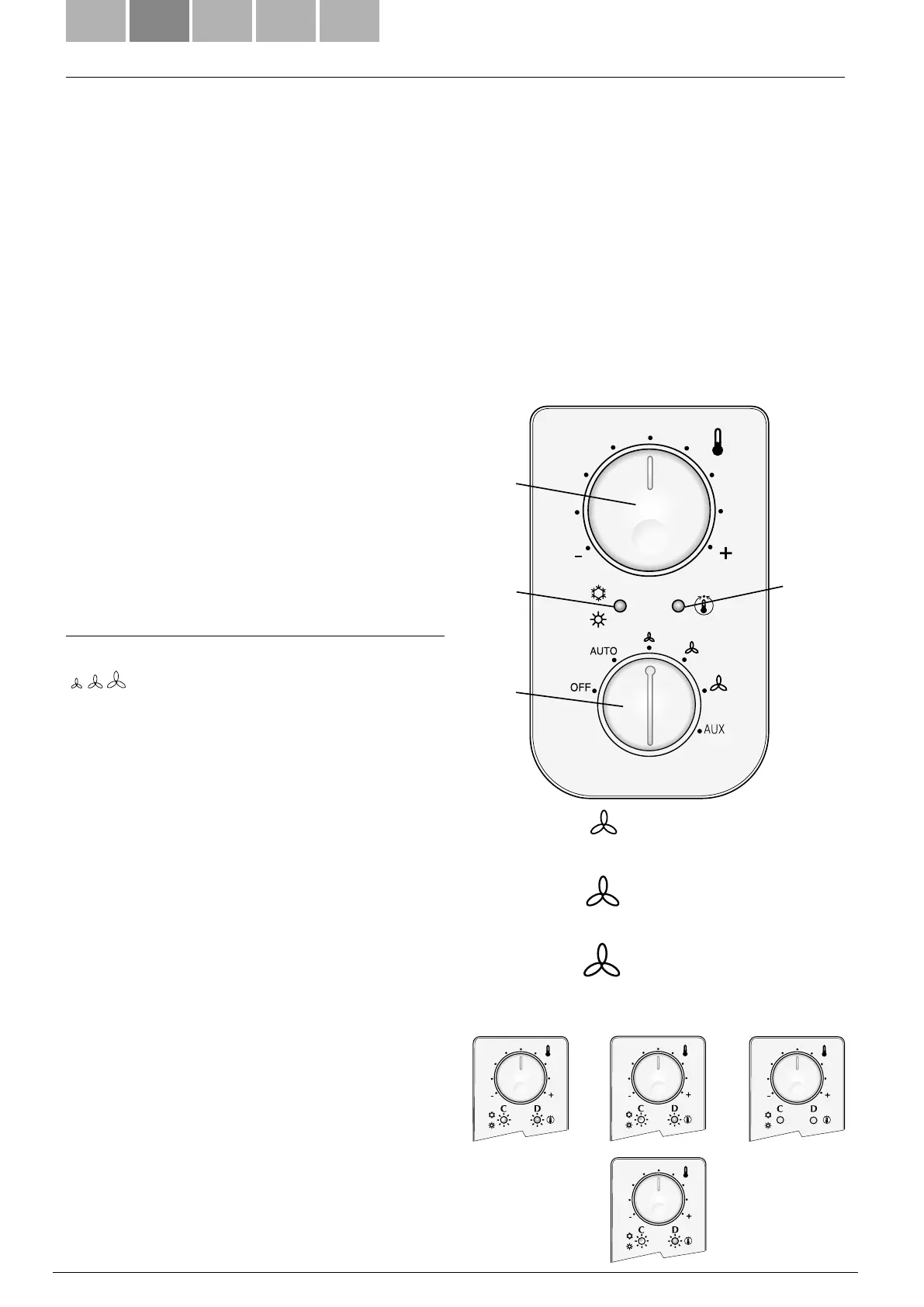
The panel features :
(A) ON-OFF selector and ventilation mode;
(B) temperature selector switch;
(C) operating mode LED indicator lamp (blue, red and
pink);
(D) yellow LED led indicating ventilation request
(or operating faults if blinking).
PRODUCT DESCRIPTION
USE
CONTROLS:
Speed selector switch (A)
OFF The fan coil is off. But it can restart in Hot mode (Anti-
freeze function) if the room temperature drops below 7°C
and the water temperature is suitable, in this case the red LED
flashes.
AUTO The thermostat maintains the setting temperature by
adjusting fan speed in Automatic Mode, according to the room
temperature and the temperature setting.
The thermostat maintains the setting temperature by switch-
on and off cycling, using respectively the minimum, medium
or maximum speed of the fan.
AUX Auxiliary operation mode “Sleep”/Activation of the
purification accessory
Temperature Selector Switch (B)
Use to make the required temperature setting.
The temperature corresponding to the selector switch set in
the central position, depends on the active operation mode
(Hot 20°C, Cold 25°C, Anti-freeze 9°C).
The maximum and minimum temperature deviations from the
central position are +8 C and -8 C.
Displays CD
The LED indicator lamp C changes colour to indicate the cur-
rent operating mode:
RED: Hot (heating),
BLUE: Cold (cooling),
PINK: when blinking, it indicates that water in the system has
not yet reached the temperature required to enable ventila-
tion,
YELLOW: when on it indicates that ventilation request is acti-
vated. When blinking, it indicates that a room probe operating
fault has been detected (Emergency Mode).
V1 = Minimum speed
V2 = Medium speed
V3 = Maximum speed
A
B
C
D
Antifreeze
Heating
Cooling
22 °C
30 °C14 °C
9 °C9 °C
9 °C
25 °C
33 °C17 °C
28 °C12 °C
20 °C
Dead zone 5°C
Dead zone 2°C