IT EN FR DE ES
17IFCZ-ACTALJ 1807- 4696520_04
WARNING: check that the power supply is disconnected before
performing operations on the unit.
WARNING: the electrical connections, the installation of the fan coils
and relevant accessories should be performed by a technician who
has the necessary technical and professional expertise to install,
modify, extend and maintain plants, and who is able to check the
plants for the purposes of safety and correct operation.
The fancoil should be installed in such a way as to facilitate routine (filter
cleaning) and special maintenance operations, as well as access to the air
breather valve on the side of the unit frame (connector side).
The assembly site must be chosen in such a way that the maximum and
minimum ambient temperature limits are respected 0÷45°C (<85% U.R.).
To install the unit, proceed as follows
(See drawings p. 34)
:
- Remove the air filter .
- Undo the screws and remove the housing .
- In case of wall-mounted FCZ-ACT unit, keep a minimum clearance of
80 mm from the floor. In the case of floor-mounted units on feet, refer
to the instructions supplied with the accessory.
- Use expansion plugs (not supplied) to secure the unit to the wall as
indicated in .
- Make hydraulic connections.
Refer to the dimensional data for the position and diameter of the
hydraulic connections.
Insulate water lines adequately or fit the auxiliary condensate
drainage tray (available as an accessory) to prevent dripping during
cooling applications.
The condensate drain system should be of an adequate size and
be positioned to favour runoff (min. 1% slope). If condensate is
drained into the sewage system, install a siphon to prevent return of
unpleasant odour into the room.
- Make the electrical wirings as shown in the wiring diagrams.
- Refit the air filter.
WARNING: check that the power supply is disconnected before
performing operations on the unit.
WARNING: the electrical connections, the installation of the fan
coils and relevant accessories should be performed by a technician
who has the necessary technical and professional expertise to
install, modify, extend and maintain plants, and who is able to
check the plants for the purposes of safety and correct operation.
CONNECTION CABLES SPECIFICATIONS
Use H05V-K or N07V-K type cables with 300/500 V with insulation, piped
or ducted.
All the cables must be piped or ducted until they are inside the fan coil.
The cables coming out of the pipe or duct must not be subject to
stretch or twist. They must be protected from weather conditions.
Stranded wires can only be used with terminating sleeves. Make
sure that the strands of the wires are inserted properly.
When making the connections, follow the wiring diagrams supplied
with the equipment and shown in this document.
Wiring diagrams are constantly updated. It is therefore compulsory to
refer to the ones supplied with the unit.
To protect the unit against short circuits, fit an omnipolar magneto-
thermal trip 2A 250V (IG) to the power line with a minimum contact
opening distance of 3 mm.
Each control panel can control a single fan coil.
The control panels only comprise electric circuits connected to a power
supply of 230V;
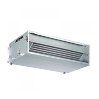
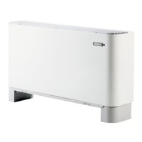
UNIT INSTALLATION
ELECTRICAL CONNECTIONS
If hydraulic connections require the rotation of the coil, remove the
cover or the front panel and proceed as follows
(See drawings Fig.
2- 6
p.
34):
– disconnect the electrical wirings from the control board, remove the
circuit card from the panel on the right;
– undo the screws and remove the coil case (fig2. p.39);
– remove the screws securing the coil, then remove the coil;
– remove the push-outs on the right-hand side;
– rotate the coil and secure it it with the screws previously removed;
– refit the cover, secure it with the screws, then insert the plastic plugs
supplied in the holes left free by the hydraulic connections; all the trays
can be used to collect condensate on both sides. In case of vertical
installation, to discharge condensate on the right side, position the drain
connection to the right.
– slide out the electrical connection from the right-hand sided, remove
the push-out and move the cable guide from the right to the left side;
– transfer the electrical wirings to the left side through the cable guide;
– move the control board and the ground jumper connection to the left
side;
– refit the control card on the left side and reconnect the electrical wirings;
ROTATING THE COIL