22
Other thermal
Number Mode Note Required accessories
Logic 2
Heating Available RT5 temperature sensor
ACS Available Extra 3-way valve, water tank sensor
Heating + DHW Available Extra 3-way valve, RT5 temperature sensor, Water tank sensor
Logic 3
Heating Available
/
ACS Available
/
Heating + DHW Available
/
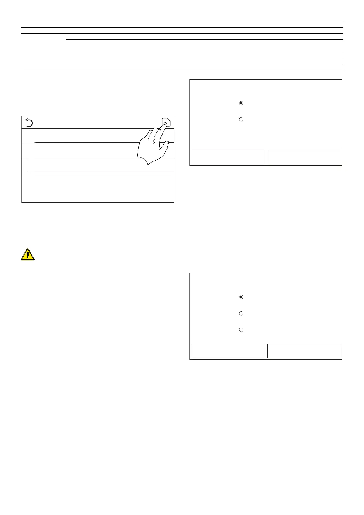
6.8 SETTING AN ADDITIONAL HEATER OPTIONAL
EHEATER
At the commissioning parameter setting page, by touching “Optional E-Heater”, the
control panel will access to the corresponding setting page.
Optional E Heater
Optional E Heater: 1
T Heater: -15°C
Logic 1
Once you have entered the “Optional elec. heater” function, you can activate or
deactivate any additional electric heater. This heater may be single-stage or du-
al-stage (in the case of a dual-stage model, you can decide whether or not to use
both stages by specifying the number of heaters in the rst parameter). You can
also set the outdoor temperature threshold below which it will be activated in place
of the heat pump.
WARNING: it is compulsory to select “Logic 1”.
Lastly, press the top right button to save the data entered.
Note:
— When this function is activated, it permits the activation of the supplementa-
ry heaters (via a 230V ~ 50Hz signal to the "KM1" and "KM2" terminals; in the
case of a single heater, use the "KM1" terminals only) if the outside temperature
falls below the value specied in the “Elec. heater T." parameter or if “Emergency
mode” is activated;
— The supplementary water probe must be installed downstream of the electric
heater (for more information, refer to the installation manual);
— If this function is used, no additional heat source can be enabled (Additional
heat source);
— The electric heater must be installed downstream of the 3-way valve (terminal
side of the system);
— The DHW request will be met by the electric heater in the compatible Aermec
accessory tank, whereas the system request will be met by the electric heaters;
— There are two working logics for this function:
Logic 1: the heat pump and the optional electric heater cannot be started at the
same time.
Logic 2: the heat pump and the optional electric heater can be started at the same
time when the ambient temperature is lower than T-Eheater.
— The electric heaters for the system, and the electric heater in the DHW tank
available as an Aermec accessory, will never be activated simultaneously;
— If the relative function is activated (paragraph "8.1 Activating/deactivating
the memory (On/o memory)p.32"), the value of these parameters will be
stored in the memory and automatically reset after any possible voltage failure.
6.9 SETTING THE INSTALLATION OF THE REMOTE ROOM
TEMPERATURE PROBE AMBIENT SENSOR
At the commissioning parameter setting page, by touching “Remote sensor”, the
control panel will access to the corresponding setting page, where it can be set to
“With” or “Without”.
Remote sensor
With
Without
OK Cancel
After accessing the “Ambient sensor” function, you can specify whether or not to
enable the remote room temperature probe (for more information about this com-
ponent, refer to the installation manual).
Note:
— The “T-remote room“ option in the “Ctrl.state“ function will only be available if
the room temperature sensor is enabled;
— If the relative function is activated (paragraph "8.1 Activating/deactivating
the memory (On/o memory)p.32"), the value of these parameters will be
stored in the memory and automatically reset after any possible voltage failure.
6.10 AIR REMOVAL
At the commissioning parameter setting page, by touching “Air removal”, the con-
trol panel will access to the corresponding setting page, where it can be set to “On”
or “O”.
Air removal
Air
Water tank
O
OK Cancel
After accessing the “Air removal” function, you can activate water circulation (in the
selected circuit) to eliminate any air from the circuit. Select the required logic, then
press “OK” to conrm.
Note:
— This function can only be activated if the unit is switched O. In addition, this
function must be disabled before the unit can be switched On;
— If the relative function is activated (paragraph "8.1 Activating/deactivating
the memory (On/o memory)p.32"), the value of these parameters will be
stored in the memory and automatically reset after any possible voltage failure.