24
6.12 MANUAL DEFROSTING
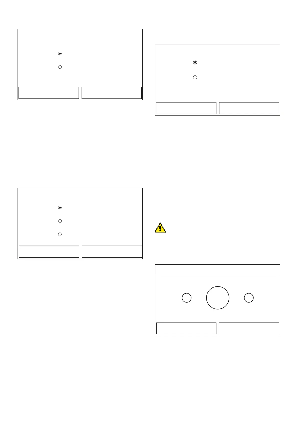
Manual defrost
On
O
OK Cancel
After accessing the "Manual defrost" function, you can activate or deactivate the
command for forced execution of a defrost cycle. Make your selection, then press
“OK” to conrm.
Note:
— This function can only be activated if the unit is switched O;
— The defrosting cycle is automatically interrupted if the defrosting temperature
rises above 20°C, or in any case after 10 minutes;
— If the relative function is activated (paragraph "8.1 Activating/deactivating
the memory (On/o memory)p.32"), the value of these parameters will be
stored in the memory and automatically reset after any possible voltage failure.
6.13 FORCE MODE
At the commissioning parameter setting page, by touching “Force mode”, the con-
trol panel will access to the corresponding setting page.
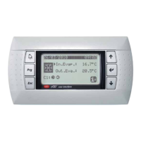
Force mode
Force cool
Force heat
O
OK Cancel
After accessing the "Force mode" function, you can activate or deactivate the com-
mand to execute the specic heating or cooling function.
The function can be set to “Force-cool”, ‘Force-heat”, and “O”. When it is set to
“Force-cool” or “Force-heat”, the control panel will directly go back to the menu
page and response to any touching operation except the ON/OFF operation. In this
case, by touching ON/OFF, “Force mode” will quit.
Note:
— This function can only be activated if the unit is switched O after a re-start;
— The unit status (On/O) cannot be modied while this function is in progress;
— If the relative function is activated (paragraph "8.1 Activating/deactivating
the memory (On/o memory)p.32"), the value of these parameters will be
stored in the memory and automatically reset after any possible voltage failure.
6.14 ACTIVATING AUXILIARY DEVICE MANAGEMENT GATE
CTRL
At the commissioning parameter setting page, by touching “Gate-Ctrl.”, the control
panel will access to the corresponding setting page.
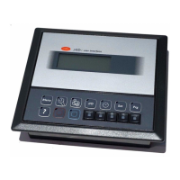
Gate Ctrl.
On
O
OK Cancel
After accessing the “Gate-Ctrl” function, you can activate or deactivate the manage-
ment of the switch-on/switch-o command via the external contact (for more in-
formation about this contact, refer to the installation manual). Make your selection,
then press “OK” to conrm.
Note:
— When “Gate-Ctrl.” has been activated; the display panel will detect the card
state. When the card has inserted, the unit will run normally. When the card is
drawn out, the controller will turn o the unit at once and back to the home-
page. In this case, all touching operation become ineective, and a prompt di-
alog box will pop up. The unit will resume normal operation until the card has
inserted back and the ON/OFF status of the control panel will resume to that
before the card is drawn out;
— If the relative function is activated (paragraph "8.1 Activating/deactivating
the memory (On/o memory)p.32"), the value of these parameters will be
stored in the memory and automatically reset after any possible voltage failure.
6.15 SETTING OF MAX. ABSORPTION A/P LIMIT
Function currently NOT AVAILABLE.
WARNING: this function is not currently available, so its setting must nec-
essarily be “Without”.
6.16 SETTING THE SERIAL ADDRESS OF THE UNIT
ADDRESS
+-
1
OK Cancel
Address
Range: 1~153 Default: 1
After accessing the “Address” function, you can set the address assigned to the unit
for possible control via Modbus. To set the required value, use the "+" and "-" keys,
entering a value within the permitted range. After setting the value, press “OK” to
conrm and return to the higher level.
Note:
1. The unit can be used to create a BMS supervision system with the Modbus
protocol (for more information, refer to the specic documentation available
on the website);
2. If the relative function is activated (paragraph "8.1 Activating/deactivating
the memory (On/o memory) p. 32"), the value of these parameters will
be stored in the memory and automatically reset after any possible voltage
failure;