12 22.11 5806712_07
4 MINIMUM TECHNICAL SPACES
For all units, it is fundamental to respect the minimum distances in order to guarantee optimal ventilation to the nned heat exchanger coils to avoid the following:
— The generation of hazardous atmospheres in the case of refrigerant gas leaks;
— Return of hot air;
— Insucient air ow to the nned heat exchanger coils.
Each side of the unit must have space to allow all routine and extraordinary maintenance to be performed.
The air suction inlet and the vertical air exhaust must not be obstructed.
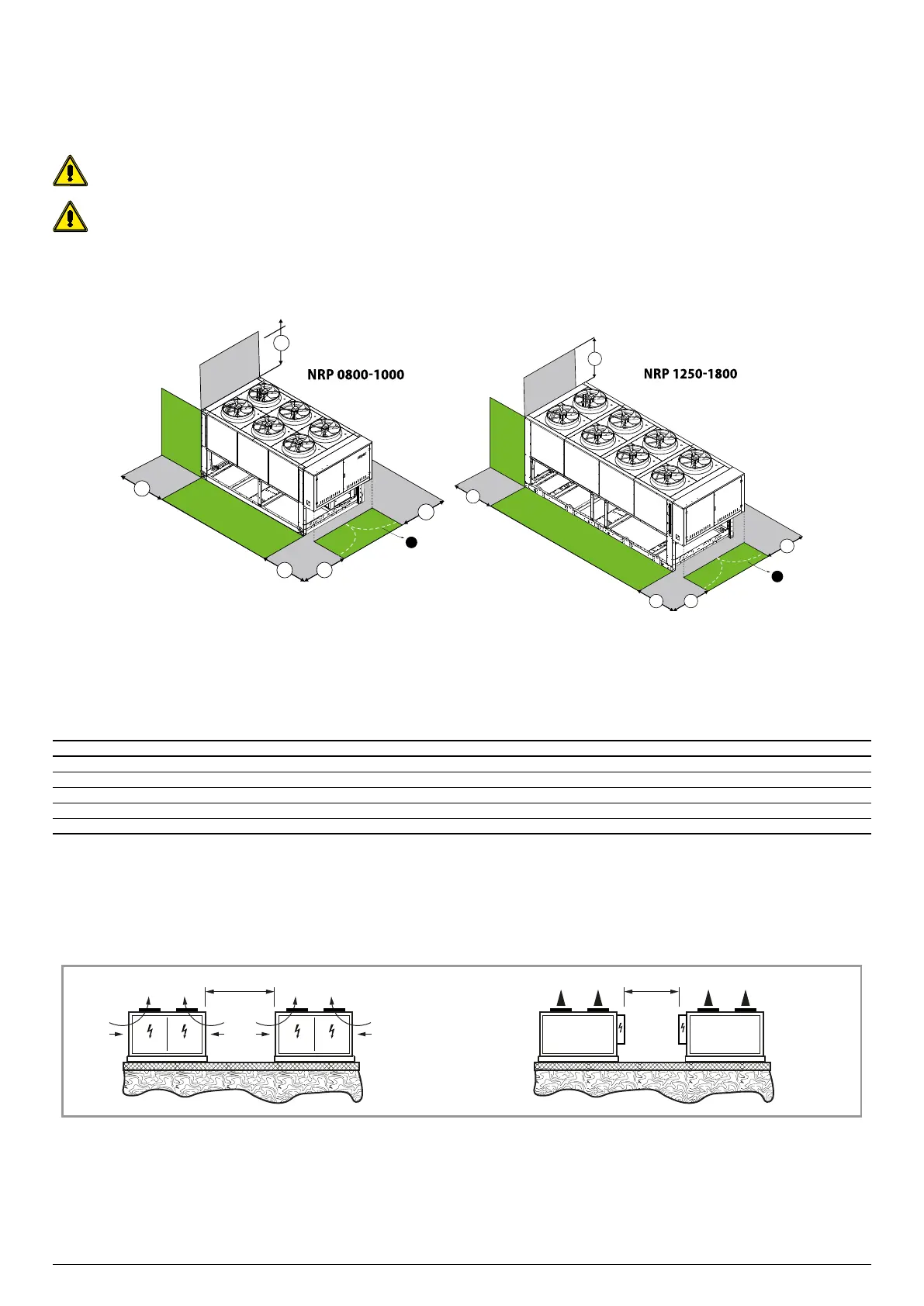
The following images indicate the minimum required space:
SINGLE INSTALLATION
1 42 in
C1
C2
B1
C2
A1
1
1
1
1
* Minimum technical space, to be ensured in order for the chiller to work properly and for possible maintenance.
The drawings are provided solely as examples.
VERSION A
Size 0800 0900 1000 1250 1400 1500 1650 1800
Minimum technical spaces
B1 A in 31.5 31.5 31.5 31.5 31.5 31.5 31.5 31.5
B2 A in 43.3 43.3 43.3 43.3 43.3 43.3 43.3 43.3
C1 A in 31.5 31.5 31.5 31.5 31.5 31.5 31.5 31.5
C2 A in 31.5 31.5 31.5 31.5 31.5 31.5 31.5 31.5
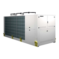
MULTIPLE INSTALLATION
The minimum distances indicated above guarantee unit operation in the majority of applications. There are however specic situations that involve the installation of multiple
units:
A 91 in B 59 in
A B