47
IVES0LJ 1707 - 5880761_01
The fan coil tray has 2 condensate drains
on the right and left side.
We recommend using the condensate
drain fitting on the side of the hydraulic
connections.
Install the drain condensate drain fitting
supplied. Seal the connection between
the tray and the fitting with silicone.
Seal the drain that is not used.
Connect the tray fitting to the condensate
drain network. Use a drain pipe, which
must be fixed to the tray fitting. The
drain fittings are designed only to be
fixed to hoses with suitable inner
diameter. Avoid the application of
greater loads and do not use them for
other purposes.
Make sure that the drain not used is
closed and does not leak.
The condensate drain network must be
properly sized and the pipelines must
be positioned in order to maintain a
suitable slope along the path (min.1%).
In the case of discharge to the sewer, it
is advisable to make a siphon which
prevents odours from returning into the
environment.
Run an operating and condensate drain
system seal test by pouring water in the
tray.
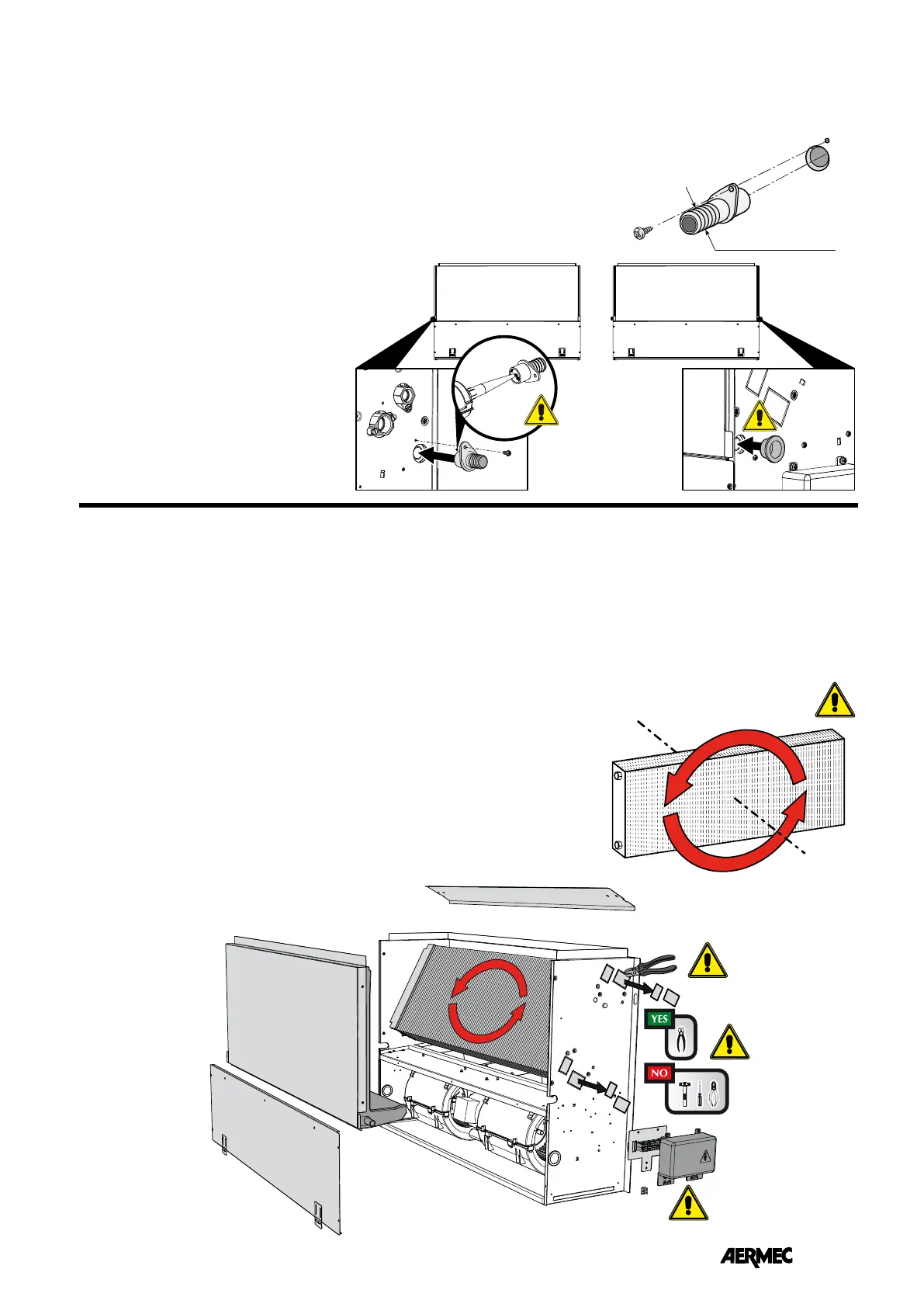
CONDENSATE DRAIN
Should the coil rotate due to the hydraulic
connection, remove the front closing
panel and proceed as follows:
– Remove the condensate collection tray.
– Remove the cover from the coil by
loosening the screws.
– Remove the screws that fasten the coil
and remove the latter.
– Remove the push-out elements from the
right side.
– ATTENTION! Before rotating the coil,
refer to the coil rotation diagram.
The coil must be rotated and installed
correctly.
Rotate the coil correctly and fix it with the
previously removed screws. The spaces
between manifold and hole on the side
must be filled and sealed with insulation
material.
– Remount the cover on the coil by
fastening the screws.
- Close the holes left free from the
hydraulic connections on the left side
with insulation material.
- Remount the condensate collection tray.
The tray is set up for the condensate
drain on both sides. We recommend
using the condensate drain fitting on the
side of the hydraulic connections.
Make sure that the drain not used is
closed and does not leak.
– Remove the electrical connections from
the right side.
– Move the electrical connections to the
left side passing them through the cable
gland.
– Move the support plate, terminal board,
earthing jumper, and electrical devices
from the right to the left side.
- Remount the front closing panel.
COIL ROTATION
A
B
180°
COIL ROTATION DIAGRAM
ext. Ø 20.5mm
 Loading...