7
IVES0LJ 1707 - 5880761_01
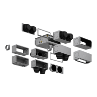
MAIN COMPONENTS
SYSTEM TYPES
The fan coils are designed for 2 and 4-pipe
systems with fixed or variable flow rate,
in the following versions:
- with 3 rows and with 4 rows;
- 3 Rows plus a 1-row coil (BV).
VENTILATION
Ventilation is controlled from a control
panel (accessory).
The motorised 6-7-speed fan allows the
control panel to be connected to the
3 speeds that produce the ideal useful
static pressure values for the system.
HEAT EXCHANGE COIL
Main 3 and 4-row coil. One-row heating-
only coil. Coil with low pressure drops,
made with copper pipe and aluminium
corrugated louvred fins, blocked by the
mechanical expansion of the pipes. The
manifolds are equipped with female
hydraulic connections and air vents on
the upper part of the coil.
FILTERING SECTION
Intake air filter, easy to remove for
per iodical cleaning. M a de with
renewable raw materials, it can be
cleaned with a suction device.
G3 filtration class. Flame behaviour M1 NF
F 16-101.
ELECTRIC FAN UNIT
Centrifugal fans with dual intake and fans
designed for low noise emission.
The fans are coupled directly with the
electric motor shaft.
The 5-speed motorised fan gives the
possibility to select the 3 favourite
speeds, by changing the settings in the
electric box on the motor.
The electric motor is buffered with elastic
supports.
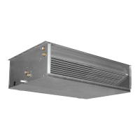
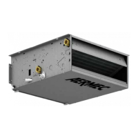
STRUCTURE
It is made with galvanised sheet metal
of suitable thickness. Internal insulation
Class 1.
Slots for installation are on the rear side.
The intake and flow inlets connect the fan
coil to any type of air ducting.
The flow inlet includes the connection
flange.
CONDENSATE DRAIN
Every device is equipped with a
condensate drip tray for vertical and
horizontal installation. The fan coil tray
has 2 condensate drains on the right
and left side. We recommend using the
condensate drain fitting on the side of
the hydraulic connections.
HYDRAULIC CONNECTIONS
The connections on the left side are for
female fittings. The coil can be rotated to
take the connections to the right side. The
coil can be rotated on site.
CONTROL PANEL
There are various control panels available
in order to select the most suitable one
for the system.
By combining the control panels, the
thermostats and the other accessories of
the VMF series, you can make full use of
the VES units' potential.
The thermostats of the VMF series ensure:
- Control of a single unit and accessories.
- Control of a network of 6 units, of which a
master one with a thermostat and control
panel plus 5 slave units equipped with a
thermostat, which operate according to the
environmental conditions.
- Control of the VES unit in a complex
network of up to 64 areas with 6 fan coils
(up to 384 fan coils with one VMF-E5
control board).
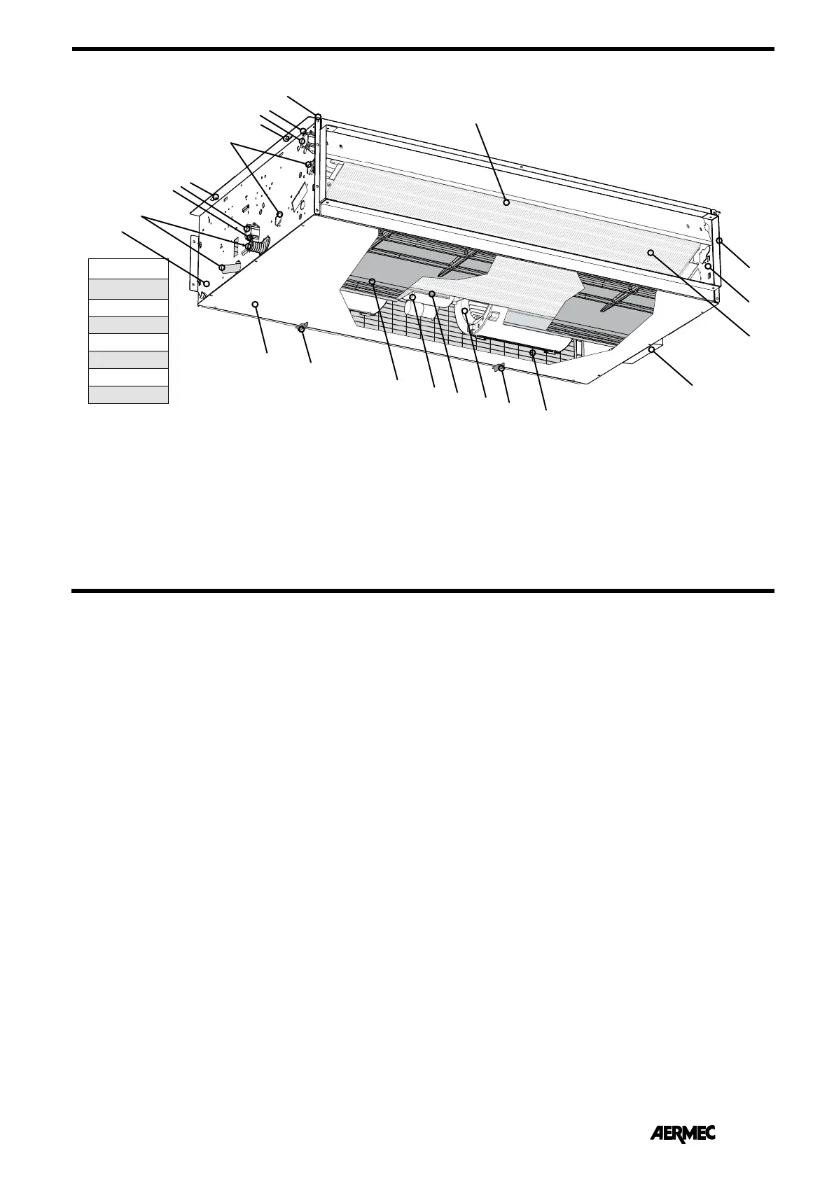
DESCRIPTION OF THE COMPONENTS
VES 030
VES 040
VES 130
VES 140
VES 230
VES 240
VES 330
VES 340
2
3
1
4
6
17
13
11
14
15
16
10
11
5
7
8
9
18
19
12
5
20
21
1 Air delivery
2 Frame (support structure)
3 Air vents on the coil
4 Hydraulic connections (water outlet)
5 Fixing slots
6 Hot water coil set-up
7 Hydraulic connections (water inlet)
8 Water drain on the coil
9 Condensate drain
10 Left side (bearing structure)
11 Closure panel
12 Filter retainer
13 Condensate drip tray
14 Electric motor
15 Connection box of the electric motor
16 Centrifugal fan
17 Air filter (intake)
18 Box with electric connections
19 Heat exchange coil
20 Right side (bearing structure)
21 Air flow flange
 Loading...