6
IVES0LJ 1707 - 5880761_01
PURPOSE OF THE VES FAN COILS
The fan coil is a terminal used to treat air, both during winter and summer. The VES fan coils have been designed to meet any
requirement in ducted systems.
In particular, the fact that the unit can be integrated in the VMF system allows you to control the individual fan coil with accessories up
to the management of the VES inserted in complex networks of fan coils and relative accessories.
DESCRIPTION OF THE UNIT
SIZES AVAILABLE
The VES fan coils are available in:
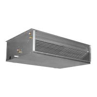
Ducted fan coils for heating, cooling, and
dehumidifying.
VES is designed to maintain the set
temperature over time while ensuring very
quiet operation. It can be installed on any
2/4-pipe system and combined with any
heat generator even at low temperatures.
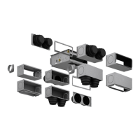
Choosing the optimal solution for any
requirement is easy thanks to the various
versions, with either a standard or bigger
coil and the possibility of horizontal or
vertical installation. The main coil, which
is reversible during installation, is designed
to ensure a high heat transfer, ideal for
applications in sensitive environments.
• Standard or bigger coil for 2-pipe systems
• Main coil and heating-only coil (accessory)
for 4-pipe systems
• 3-way valves accessories
• 2-way valve accessories for systems with
variable water flow rate.
• Wide range of useful static pressure
• Centrifugal fans in antistatic plastic. Due
to their features, they allow to reduce
the energy consumption with respect to
normal fans
• Fans with wing-shaped profile studied to
obtain high flow rate and static pressure
performance and low noise emission at the
same time
• Compatible with the VMF system
• Wide range of controls
• Wide range of accessories to satisfy all
system requirements
• Flow fitting supplied
• Class G3 air filter with easy extraction and
cleaning
• Internal insulation in Class 1 fire resistance
• IP20 protection rating
• Plastic augers, extractable for easy and
efficient cleaning
• Easy installation and maintenance
Main features of the VES fan coils
Vertical installation Horizontal installation
C/FC VC/FVCC/FC VC/FVCSAVC/FVCSA
VC/FSA
C/F
VC/FSA
C/F
SA
C/F
SA
SW
VC/FVCSA SW VC/FVCSA C/FC
SW VC/FC/FVC/FSA SWC/FSA SWC/F
SW
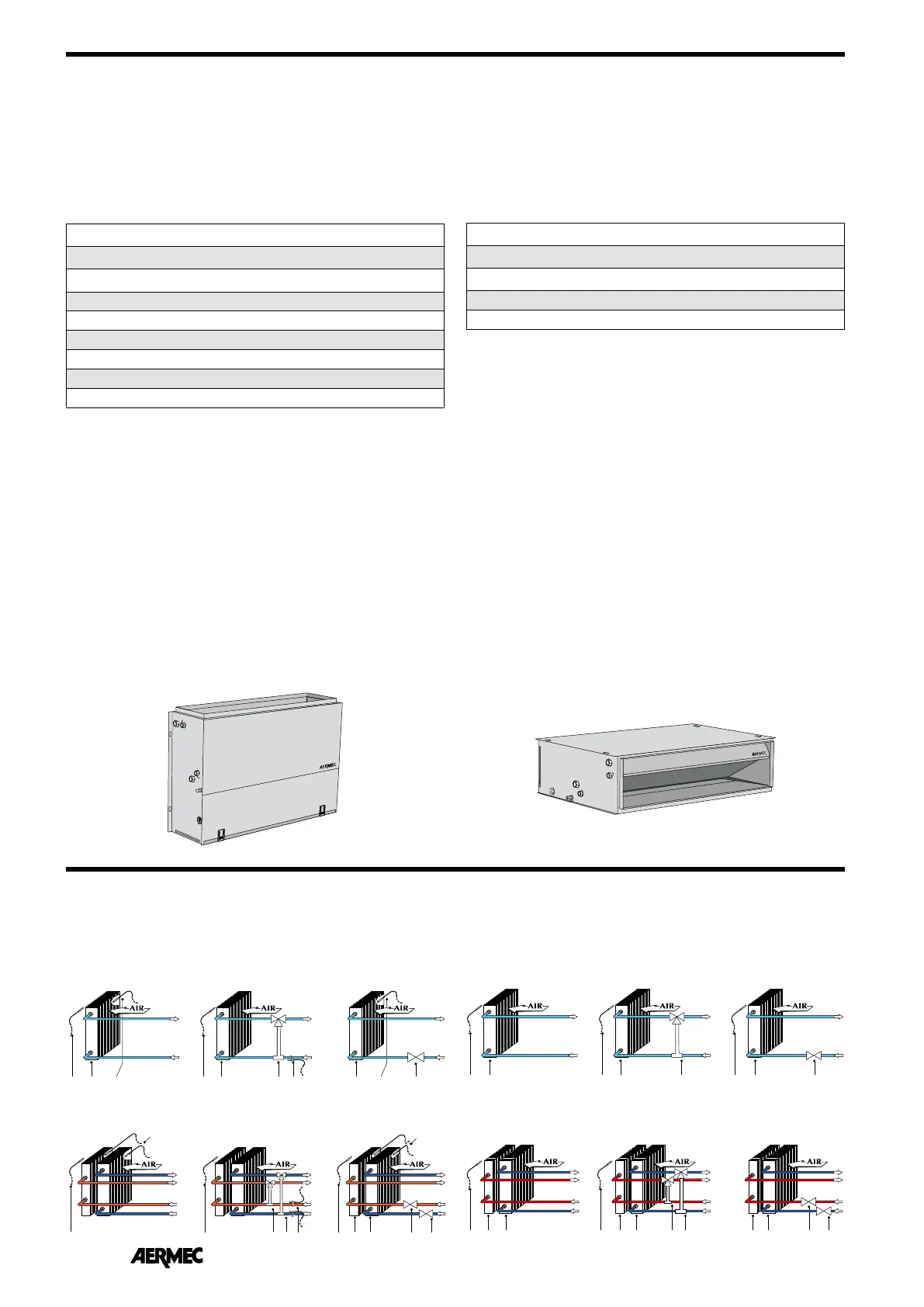
2-pipe system with water probe
SW Water temperature probe
VC/F Valve (Heating / Cooling)
VC Valve (Heating)
SA Room temperature probe
H/C Coil (Heating / Cooling)
C Coil (Heating)
SYSTEM EXAMPLES
2-pipe system without water probe
4-pipe system with water probe 4-pipe system without water probe
Key:
sizes for 2-pipe systems
VES030
VES040
VES130
VES140
VES230
VES240
VES330
VES340
sizes for 4-pipe systems (with additional heat exchanger)
VES030 + BV130
VES130 + BV230
VES230 + BV330
VES330 + BV162
 Loading...