19
NOTE:
1. Setback Function is forbidden as defaulted; you can activate or forbid Setback Function through P71 parameter setting.
2. When All Shield function of remote monitor or central controller is turned on, the wired controller can’t enter or exits from Setback Function.
3. When the unit is operating at Setback Function, the slave wired controller cannot set Save function and doesn’t display or receive Save setting.
5.18 SET THE INDOOR UNIT ADDRESS CC2
In order to use the Centrilized controller CC2 accessory correctly, each indoor unit (up to a maximum of 36) must have a dierent serial address.
Unit parameters can be set in unit On or O status:
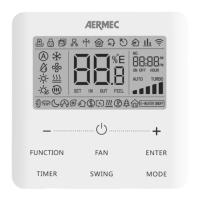
1. Press “FUNCTION” button for 5s and the temperature zone on the display will show “C00”.
2. Press “FUNCTION” button for 5 seconds once again to enter the wired contoller parameters setting page. “P00” will be shown in the temperature zone of the display.
3. Press “+” or “-” button to select parameter code “P42”.
4. Press the "MODE" button to enter the parameters setting page. The desired parameter value will ash.
5. Press “+” or “-” button to adjust the parameter value (from 1 to 36) and press “ENTER” button to exit the setting mode.
6. Press “ENTER” button to go back to previous step and nally exiting the setting parameter page.
Attention:
— To avoid communication errors, remember that dierent indoor units must have dierent serial addresses.
— It is not possible to connect more than 36 indoor units to centrilized controller CC2.
— The MINIMODBUS20 accessory (to be purchased separately) is mandatory for connecting the units to the CC2 centralized controller.
5.19 SET THE INDOOR UNIT ADDRESS BMS
To manage the indoor unit with BMS supervision system, each indoor unit (up to a maximum of 255) must have a dierent serial address.
Unit parameters can be set in unit On or O status:
1. Press “FUNCTION” button for 5s and the temperature zone on the display will show “C00”.
2. Press “FUNCTION” button for 5 seconds once again to enter the wired contoller parameters setting page. “P00” will be shown in the temperature zone of the display.
3. Press “+” or “-” button to select parameter code “P42”.
4. Press the "MODE" button to enter the parameters setting page. The desired parameter value will ash.
5. Press “+” or “-” button to adjust the parameter value ( from 1 to 255) and press “ENTER” button to end setting mode.
6. Press “ENTER” button to go back to previous step and nally exiting the setting parameter page.
Attention:
— Units cannot be connected to CC2 centralized controller and MODBUS system at the same time, only one can be selected.
— Maximum 255 indoor units can be connected in the same network.
— Before contacting any wires, make sure power is cut o.
— The MINIMODBUS20 accessory (to be purchased separately) is mandatory for connecting the units to theMODBUS system.