7
4 INSTALLATION AND STARTUP
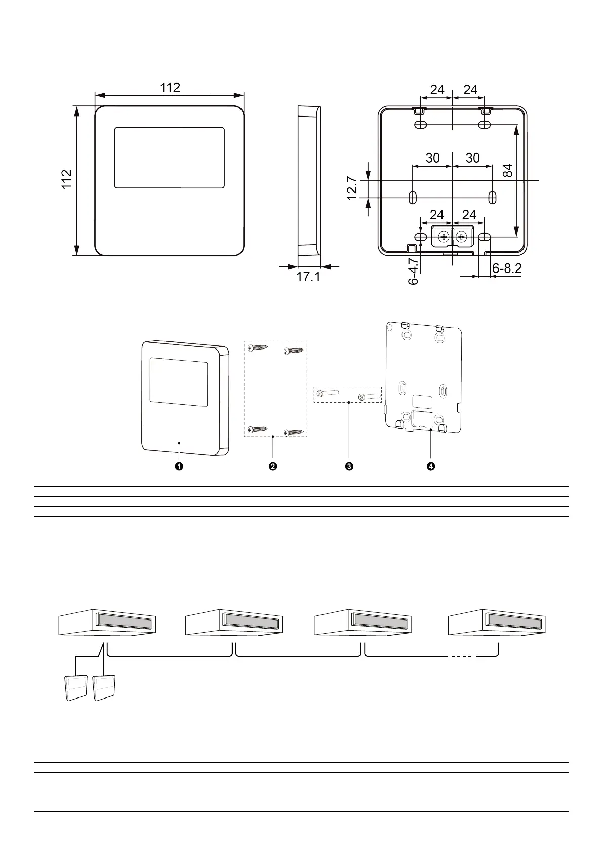
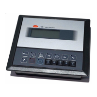
Fig. 4.1: Dimensions of Wired Controller
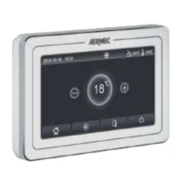
Fig. 4.2: Parts and Components of Wired Controller
N. 1 2 3 4
Name Wired Controller Self-tapping screw ST3.9×25 MA Screw M4×25 Soleplate of the Wired Controller
Quantity 1 4 2 1
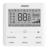
4.1 INSTRUCTION OF WIRED CONTROLLER
4.1.1 Requirements for model selection of communication wire
Fig. 4.3: Length of communication wire
L= L01+L02+L1+L2+....+L(n-1) (n≤16)
L1 L2 L(n-1)
MASTERSLAVE
L02 L01
Indoor unit Indoor unit
Indoor unit Indoor unit
Wired panel
Cable type Max lenght Size Note
Standard 2-pole cable with PVC sheath (60227 IEC
52 / 60227 IEC 53)
L ≤ 250 m
From 2 x 0,75 to 2 x 1,25
mm
2
(1) Total length of communication line can’t exceed 250m.
(2) The cord shall be Circular cord (the cores shall be twisted together).
(3) If unit is installed in places with intense magnetic eld or strong interference, it is necessary to use shielded
wire.