34
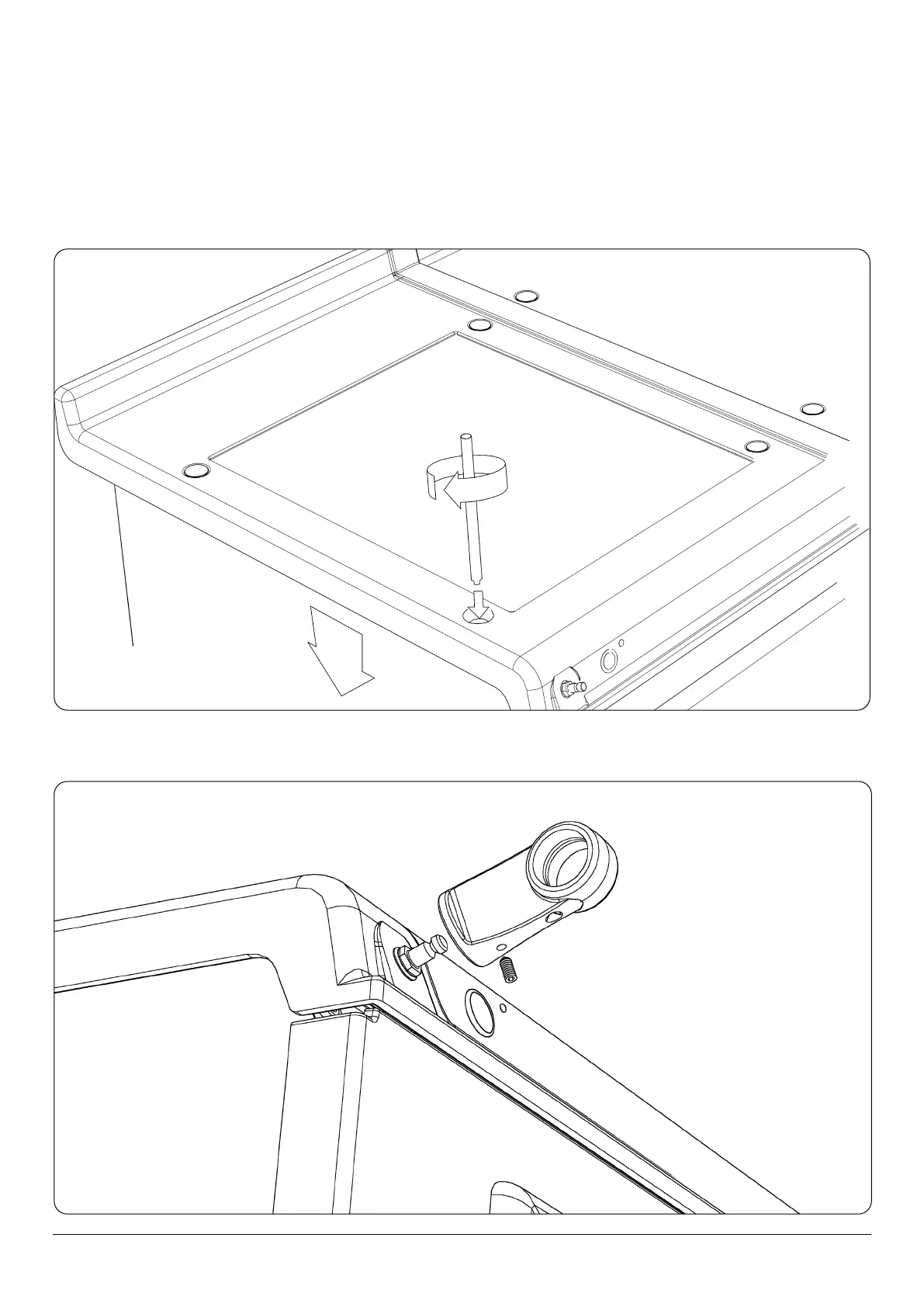
8. Using the stay rod nut adjusting tool, carefully lower the top plate adjusting nuts until the top plate sits at the required
height, making sure that the top sits level and matches the height of the AGA R7 100. (Fig. 17.9).
For servicing requirement, top plate should be removed by raising adjusters approximately ⁄” (5mm), the top plate can now
be removed easily without causing damage to the enamelled surfaces.
When removing the top plate, the switch wiring harness should be disconnected from the main wiring harness at the
connection point located at the front left hand side of the appliance, beneath the formex cover sheet.
DESN 516555
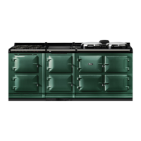
9. Fit the handrail bracket over the xing stud located on the top plate. Lock into position by tightening the grub screw
nearest the appliance. (Fig. 17.10).
DESN 516883
Fig. 17.9
Fig. 17.10