Chapter 3 Disassembly/Assembly Procedures and Parts List 55
connectors on the rear panel. Plug the cable into socket P301.
9. Locate the 8-pin cable connected to the power transformer. Move the
cable so it lays on top of the Outguard Power Supply assembly. Then
plug the cable into socket P3.
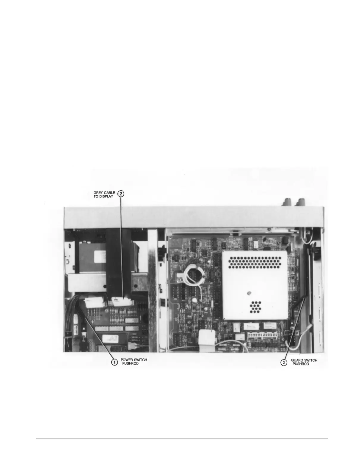
10. Locate the grey 20-pin cable connected to the Outguard Controller
assembly. Line up the cable plug with the socket on the Outguard
Power Supply assembly. Then plug it all the way in.
11. Guide the power switch pushrod through the rear of the transformer
shield's access hole. Then guide the pushrod through the rear of the
front panel's access hole. Align the pushrod with the ac power switch
shaft and push it onto the shaft.
Figure 21. Guard and Power Pushrods, and Display Cable Locations
12. Use the Covers Installation Procedure in this section of the manual to
install the 3458A bottom cover.
NOTE
The label numbers in
Figure 20 and 24
show the order of
assembly removal.
Use reverse order
for installation.

 Loading...


