6-10
Utilities
To set up the I/O port to use a controller
RS-232 Connections
The signals for the 9-pin RS-232 port on the oscilloscope is listed below.
Pin out of oscilloscope RS-232 port looking into DB9 male connector
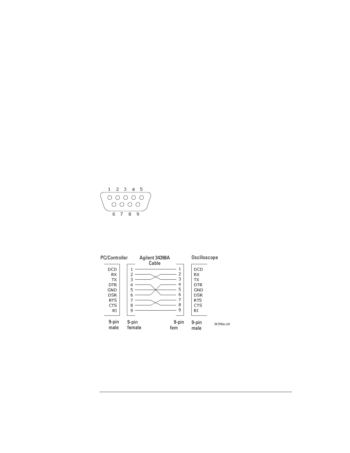
The follow figure shows the pin out of the recommended Agilent 34398A RS-232
cable.
Pin out of Agilent 34398A RS-232 cable
Pin Number Signal
1 Data Carrier Detect
2 Receive Data
3 Transmit Data
4 Data Terminal Ready
5 Signal Ground
6 Data Set Ready
7 Request to Send
8 Clear to Send
9Ring
SHELL Protective Ground
'&'
5;
7;
'75
*1'
'65
576
&76
5,
'&'
5;
7;
'75
*1'
'65
576
&76
5,
PC/Controller Agilent 34398A
Cable
Oscilloscope
9-pin
male
9-pin
male
9-pin
female
9-pin
female
 Loading...


