Chapter 2: Preparing for Use
Digital probe lead set
2–14
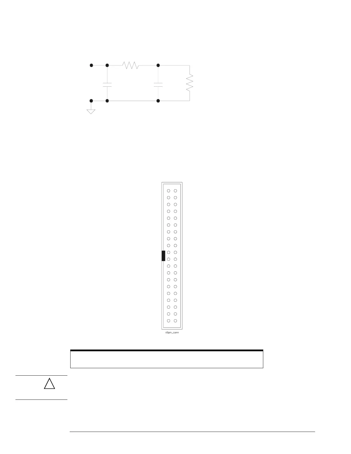
Figure 2-11
Eq
uivalent Load including oscilloscope
Direct connection through 40-pin connector
The probe cable can also be directly plugged into various 40-pin connectors on the circuit board
under test. This requires each signal pin of the 40-pin connector to have an isolation network
(Figure 2-10) on the circuit board. The pinout of the 40-pin connector is shown in Figure 2-12.
Figure 2-12
40-pin Connector Pinout
CAUTION Do not exceed the maximum input voltage rating of ±40 V peak, CAT I. The isolation network
must be used on all digital channels for this to be valid.
For more information on digital probing solutions, search for the docum
e
nt titled “Probing
Solutions for Logic Analysis Systems” (Agilent part number 5968-4632E) on the Agilent
Technologies web site at www.agilent.com.
Note: +5 V is supplied by the oscilloscope to provide power for the demo board.
DO NOT connect these pins to the circuit board under test.
7
Ω
7.4 pF1.5 pF
100 k
Ω
Signal
D0
37
D1
35
D2
33
D3
31
D4
29
D5
27
D6
25
D7
23
D8
21
D9
19
D10
17
D11
15
D12
13
D13
11
D14
9
D15
7
Do not connect
5
Unused
3
+5 V (see note)
1
+5 V (see note)
39
38
36
34
32
30
28
26
24
22
20
18
16
14
12
10
8
6
4
2
40
Power Gn
Power Gn
Signal Gnd
Signal Gnd
Signal Gnd
Signal Gnd
Signal Gnd
Signal Gnd
Signal Gnd
Signal Gnd
Signal Gnd
Signal Gnd
Signal Gnd
Signal Gnd
Signal Gnd
Signal Gnd
Signal Gnd
Signal Gnd
Signal Gnd
Signal Gnd
!
 Loading...


