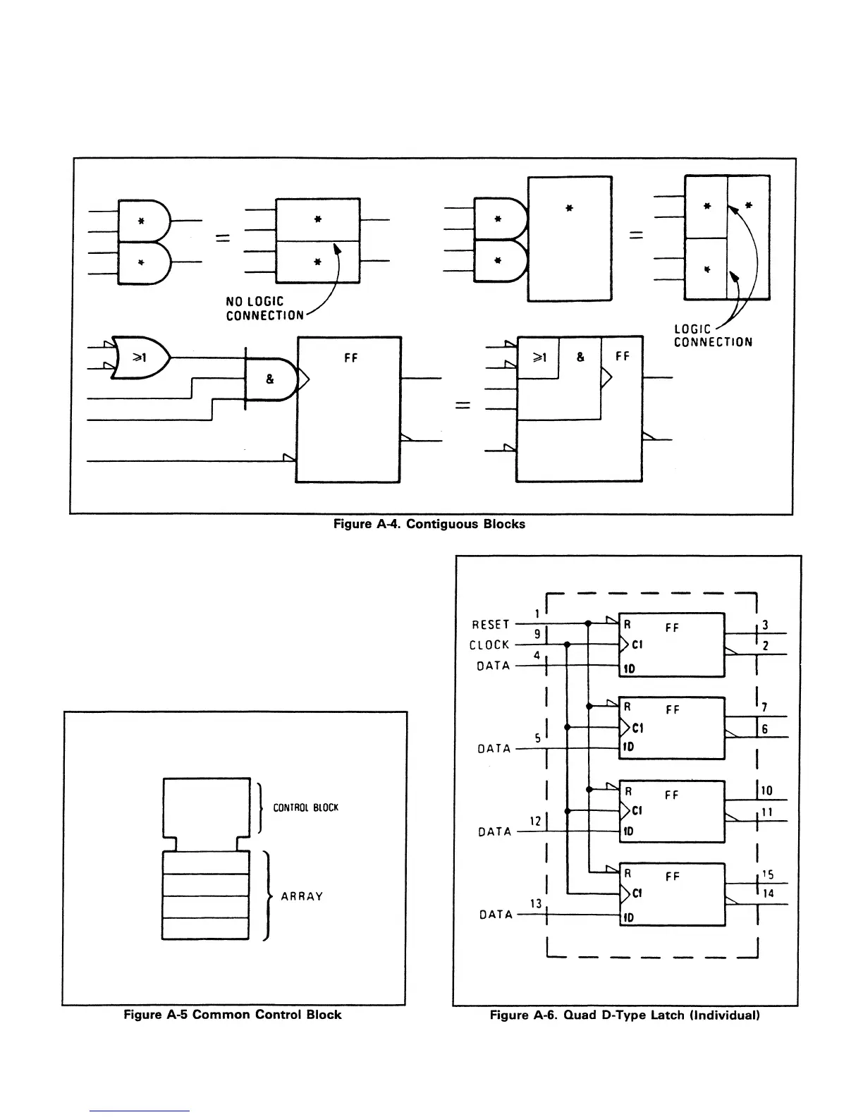
Contiguous Blocks. Two symbols may share a common
boundary parallel or perpendicular to the direction of signal
flow. Note that in the example shown in Figure A-4 there is
generally no logic connection across a horizontal line, but
Common Control Block. The Control block is used in
conjunction with an array of related symbols in order to
group common logic lines. Figure A-5 shows how the
Control block is usually represented. Figure A-6 shows a
quad D-type flip-flop with reset. This can be redrawn as
shown in Figure A-7. Note that the more complex
representation shown in Figure A-6 can be used when the
flip-flops are functionally scattered around the schematic
(i.e., not used as a quad unit).
there is always an implied logic connection cross a vertical
line. Notable exceptions to this rule are the horizontal lines
A-4
beneath control blocks and between sections of shift
registers and counters.
 Loading...


