Troubleshooting 57
Pins Description
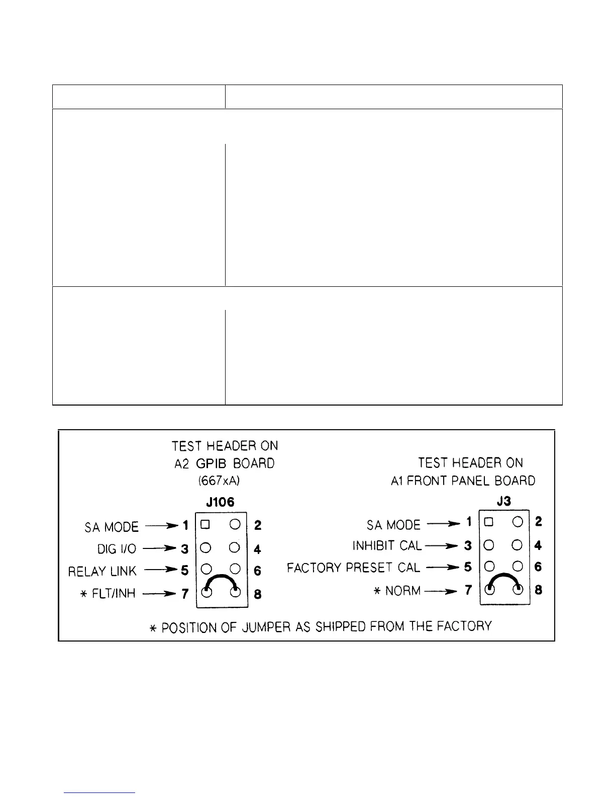
Primary Interface Test Connector A2J106 (Systems Supplies Only)
7 and 8 (FLT/INH) Normal operating (and storage) position. DIG CNTL port** is configured for
fault indicator (FLT) output and remote inhibit (RI) input .
1 and 2 (SA Mode) Install jumper here for SA mode.
3 and 4 (DIG I/O) Install jumper here to configure DIG CNTL port** for digital I/O operation .
5 and 6 (RELAY LINK) Install jumper here to configure DIG CNTL port** for control of external relay
accessories.
** See Appendix D in Power Supply Operating Manual for information about the
digital control port.
Front Panel Test Connector A1J3
7 and 8 (NORM) Normal operating (and storage) position of jumper.
1 and 2 (SA Mode) Install jumper here for SA mode.
3 and 4 (INHIBIT CAL) Install jumper here to disable calibration commands and prohibit calibration.
5 and 6 (FACTORY PRESET CAL) Install jumper here to restore original factory calibration constants.
Figure 3-15. Test Header Jumper Positions
 Loading...


