58 Troubleshooting
Table 3-5. Primary Interface SA Test
Description: These signatures check some primary interface circuits on the Systems Supply A2 GPIB Board.
Valid A2U106 ROM Firmware Revision: A.01.06
Test Setup: See Figure 3-17.
1. Turn off the power supply and remove the top cover.
2. Connect SA jumper of connector J106 on A2 GPIB Board (see Figure 3-15).
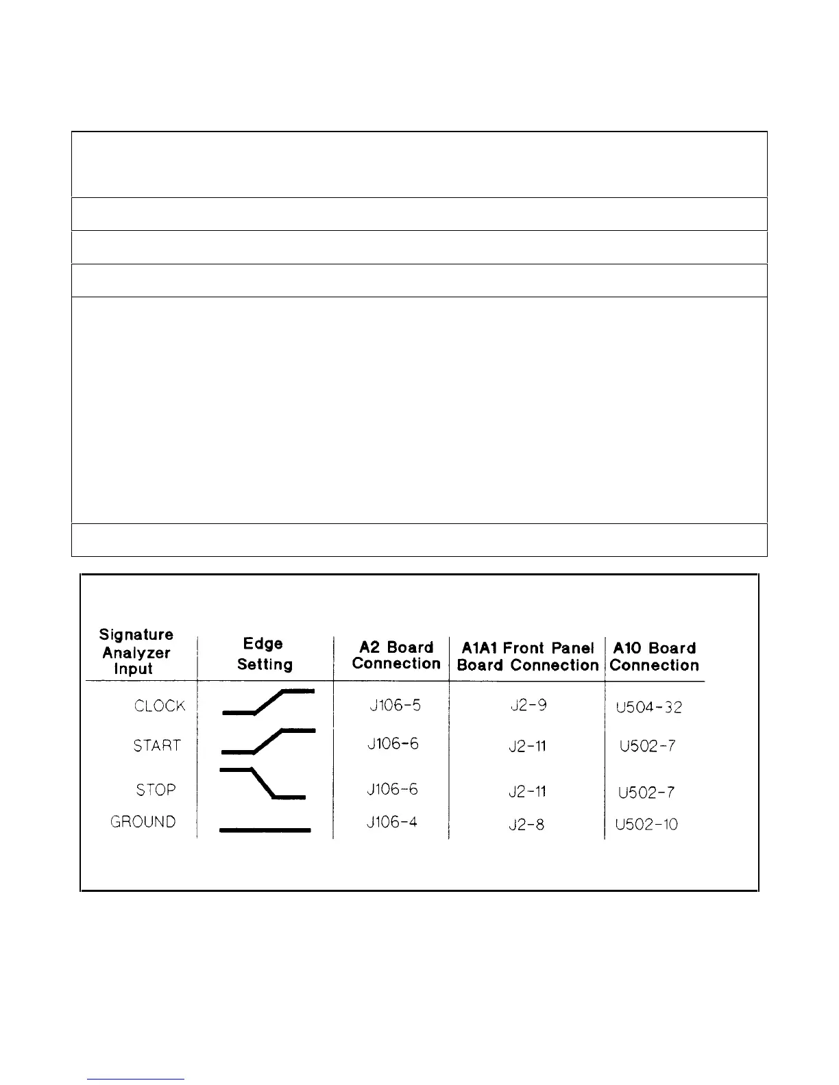
3. Connect signature analyzer CLOCK, START, STOP, and GROUND inputs as show in Figure 3- 16 .
4. Turn on the power supply and use the signature analyzer probe to take the following signatures:
Power: 5V = 9FFP
Serial Link: A2U109-3 = 0104
Microprocessor: A2U114-24 = 9FFP
A2U114-25 = UF39
Digital Control Interface: A2U118-1 = 9AF1
A2U118-9 = 40A5
A2U118-10 = 1029
A2U118-15 = 0010
A2U118-16 = 040A
Gated Array Logic: A2U119-2 = 0A55
A2U119-5 = 0040
A2U119-15 = 0040
5. After completing the tests, be sure to return the J106 jumper to its original position.
Figure 3-16. Signature Analysis Signal Inputs
 Loading...


