Installing the 81150A/81160A
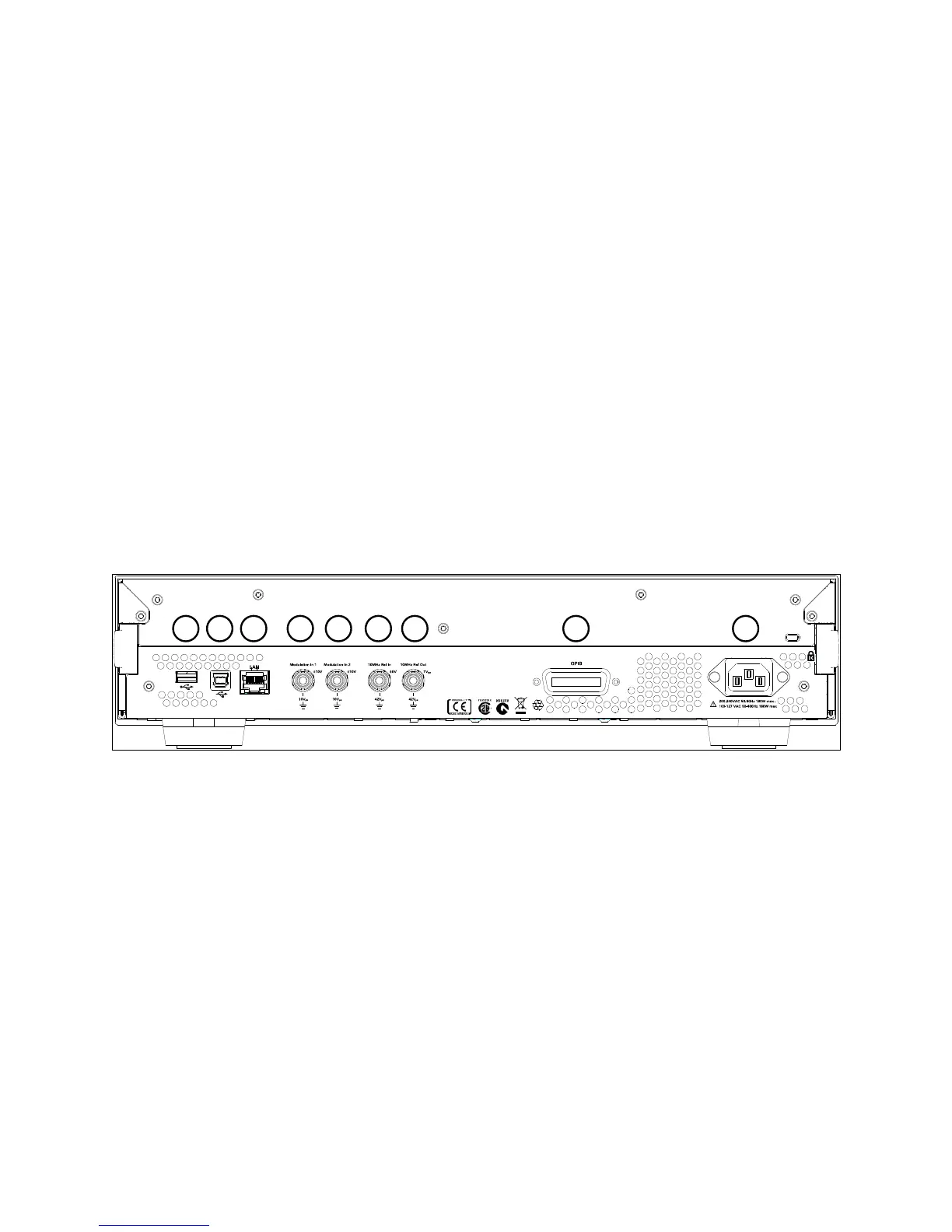
2.3 The Rear Panel
The rear panel contains:
GPIB connector
USB device connector
LAN connector
These three are used for remote control of the instrument.
Channel 1 Modulation In
Channel 2 Modulation In (2 channel instrument only)
10 MHz Clock Ref-In
10 MHz Clock Ref-Out
A USB Host Connector is used to connect external USB storage device for
storing instrument settings or software updates.
Rear panel of the 81150A
1 USB Interface Connector (Host type for external mass memory)
2 USB Interface Connector (device type for remote programming)
3 LAN Interface Connector
4 Channel 1 External Modulation Input Terminal
5 Channel 2 External Modulation Input Terminal
6 External 10 MHz Reference Input Terminal
7 10 MHz Reference output Terminal
8 GPIB Interface Connector
9 Power