130 Chapter3
Manual Adjustment Procedures
5. YTO Adjustment
5. YTO Adjustment
Assembly Adjusted
A14 frequency control assembly
Related Performance Tests
Frequency Span Accuracy Frequency Readout Accuracy and Frequency
Count Marker Accuracy
Description
The YTO main coil adjustments are made with the phase-lock loops
disabled. The YTO endpoints are adjusted to bring these points within
the capture range of the main loop. The YTO FM coil is adjusted to
place the 300 MHz CAL OUTPUT signal at the center vertical graticule
in a 20 MHz span.
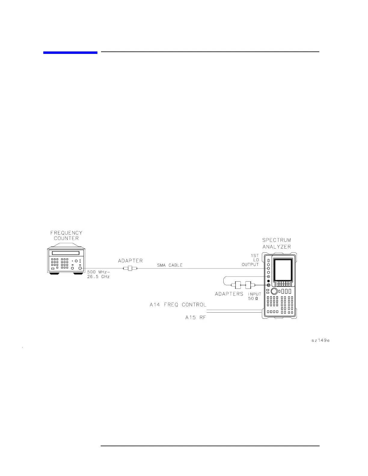
Figure 3-13 YTO Adjustment Setup