Chapter 11 525
Synthesizer Section
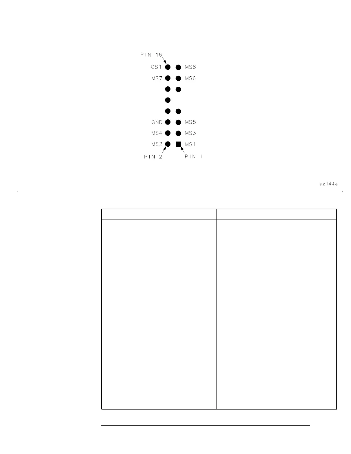
Test Connector Locations
Figure 11-2 Test Connector Pin Locations
Table 11-1 Troubleshooting Suspected Faulty Circuits
Suspected Circuit Procedure to Perform
YTO loop Confirming a Faulty Synthesizer Section
(steps 12-33)
1st LO Confirming a Faulty Synthesizer Section
(steps 9-11)
1st LO pretune frequency and amplitude Unlocked YTO PLL (steps 9-12)
Fractional N oscillator Unlocked YTO PLL (steps 13-17)
3rd LO drive Third LO Driver Amplifier (100 MHz
VCXO) (steps 1-6)
10 MHz signal at other input to reference
PLL
Unlocked Reference PLL (steps 12 and 13)
phase/frequency detector
Sampling oscillator tune voltage Confirming a Faulty Synthesizer Section
(steps 1-4)
A14 frequency control assembly Confirming a Faulty Synthesizer Section
(steps 12-18)
A14J301 10 MHz REF input Confirming a Faulty Synthesizer Section
(steps 5-8)
A15 RF assembly Confirming a Faulty Synthesizer Section
(steps 18-25)
Current source A14U307 1st LO Span Problems (All Spans) (steps
14-21)