5-12 Service Guide
Power Supply Troubleshooting 8719ET/20ET/22ET
If the Red LED of the Preregulator (A15) Is On 8719ES/20ES/22ES
RF Network Analyzers
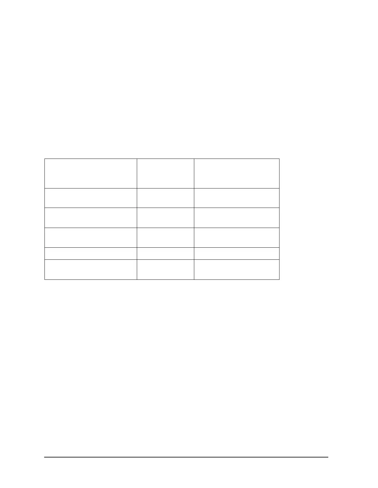
3. Remove or disconnect the assemblies listed in Table 5-3 one at a time and in the order
shown. The assemblies are sorted from most to least accessible. Table 5-3 also lists any
associated assemblies that receive power from the assembly that is being removed.
After each assembly is removed or disconnected, switch on the analyzer and observe the
red LED on the preregulator (A15).
• If the red LED goes out, then the particular assembly removed (or the one receiving
power from it) is faulty.
• If the red LED is still on after you have checked all of the assemblies listed in Table 5-3,
continue with the next section “Check the Operating Temperature.”
Check the Operating Temperature
The temperature sensing circuitry inside the preregulator (A15) may be shutting down the
supply. Make sure the temperature of the open air operating environment does not exceed
55 °C (131 °F), and that the analyzer fan is operating.
• If the fan does not seem to be operating correctly, go to “Fan Troubleshooting” on page
5-18.
• If there does not appear to be a temperature problem, it is likely that A15 is faulty.
Inspect the Motherboard
If the red LED is still on after replacement or repair of the preregulator (A15), switch off
the analyzer and inspect the motherboard for solder bridges, and other noticeable defects.
Use an ohmmeter to check for shorts. The +5VD, +5VCPU, or +5VDSENSE lines may be
bad. Refer to the block diagram at the end of this chapter and troubleshoot these suspected
power supply lines on the motherboard (A17).
Table 5-3 Recommended Order for Removal/Disconnection for Troubleshooting
the Preregulator (A15) Assembly
Assembly to Remove Removal or
Disconnection
Method
Other Assemblies that
Receive Power from the
Removed Assembly
1. Frac N Digital (A14) Remove from
Card Cage
None
2. Test Set Interface (A51) Disconnect W89 Transfer Switch (S4)
LED Front Panel (A56)
3. CPU (A7) Disconnect W91
from A7
Disk Drive (A3)
4. Display Interface (A22) Disconnect W37 Display (A18)
5. Front Panel Interface (A2) Disconnect W83
from A2
Front Panel Keyboard (A1)
 Loading...


