3-18 Service Guide
Adjustments and Correction Constants 8719ET/20ET/22ET
Output Power Adjustments 8719ES/20ES/22ES
RF Network Analyzers
5. Unplug the flexible SMB cables coming out of the source assembly cover.
NOTE The 8719ET/ES and the 8720ET/ES have two SMB cables. The 8722ET/ES
have four SMB cables. All cables are clearly marked for easy re-assembly.
6. Remove the 3 screws on source assembly cover and lift it off the frame.
7. Reattach the SMB cables to the proper connectors.
8. Turn the analyzer on. If it does not phase lock, check the cable connections.
Setting the Main Power DAC to Preset Values.
For each PEEK/POKE location listed in Table 3-2, do the following:
1. Press the following:
2. Press , enter the peek/poke address from Table 3-2, and
press .
3. Press , enter the poke value from Table 3-2, and press .
4. Repeat steps 2 and 3 for the remaining peek/poke addresses.
NOTE Your analyzer may display the message CAUTION TEST PORT OVERLOAD,
REDUCE POWER. Ignore this message and continue with the procedure.
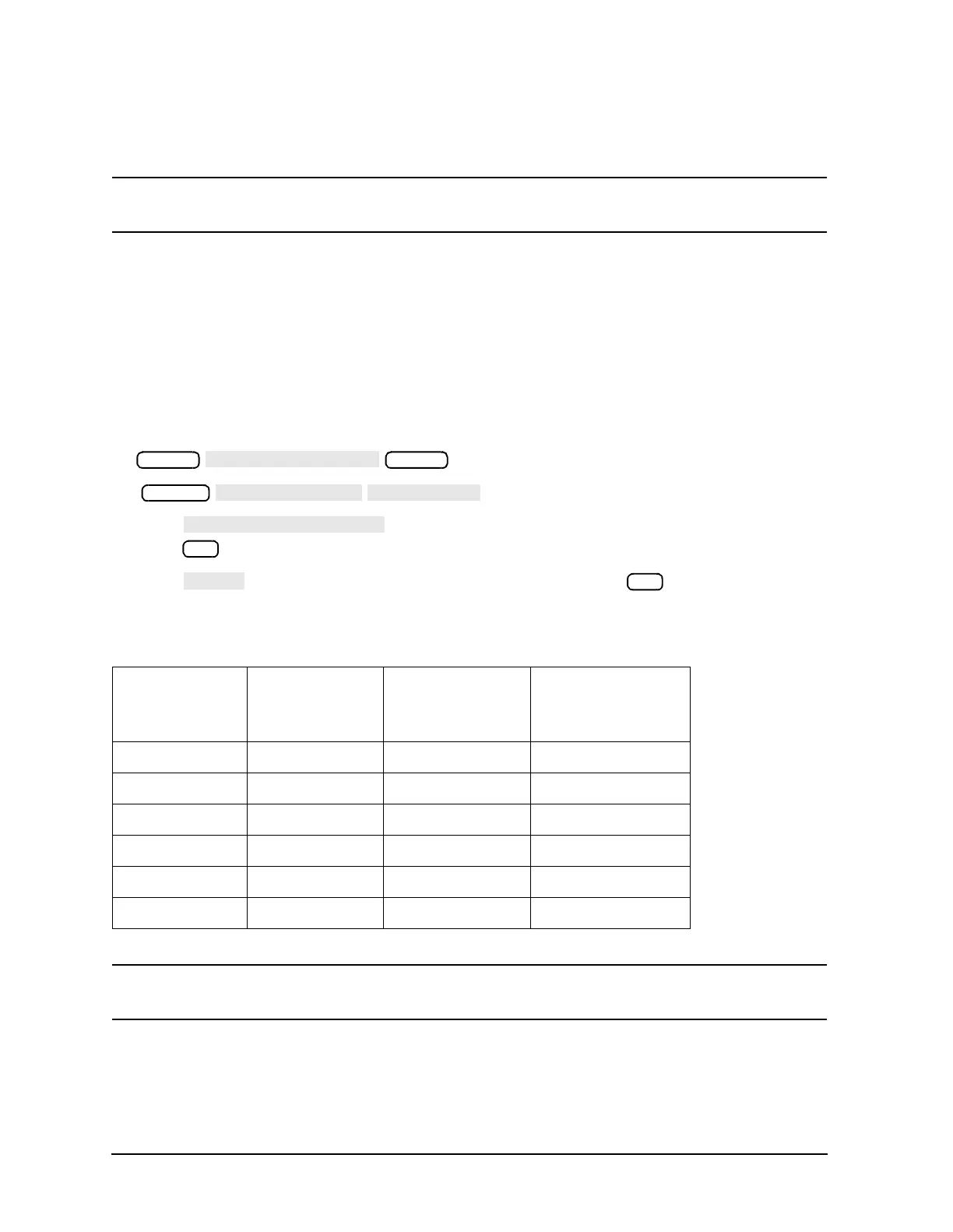
Table 3-2 Main Power DAC Peek/Poke Location Table
DAC Peek/Poke
Address
Poke Value for the
8719ET/ES
8720ET/ES
Poke Value for the
8722ET/ES
Low power 1619001442 1 1
Low power 1619001443 0 200
Mid power 1619001444 3 5
Mid power 1619001445 49 172
High Power 1619001446 10 10
High Power 1619001447 12 12
Preset
Preset
System
x1
x1
 Loading...


