Installation Note E4406-90278 11
Installation Procedure
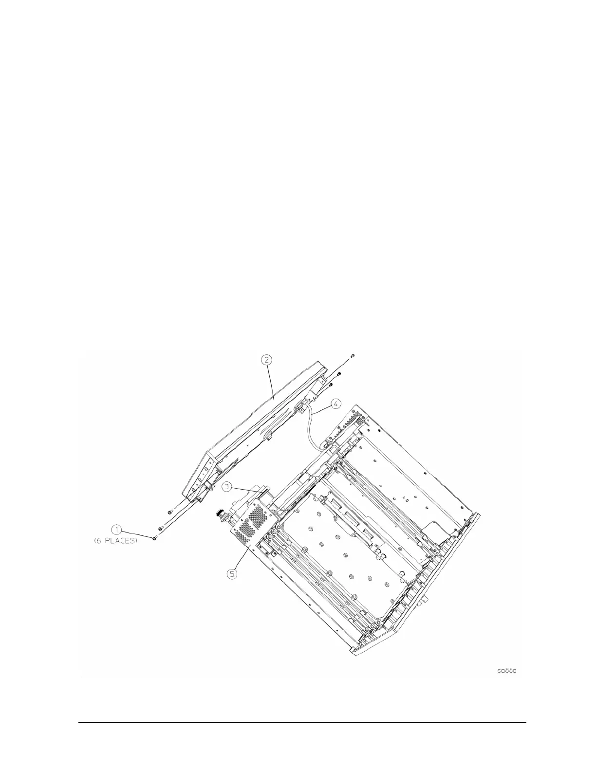
Step 8. Detach the Front Frame
1. Refer to Figure 6. Using the T-10 driver, remove the 6 screws (1) that attach the front frame
assembly (2) to the deck.
2. Disengage the green external front trigger cable (4) from the clips that secure it to the inside of
the front frame.
3. Disengage the four Base Band I/Q input cables (if present) from the clips that secure them to the
inside of the front frame.
4. Using a 9/16” socket drive, remove the nuts securing the
External Trigger Input BNC connector
and Base Band I/Q input cables (if present). Take care to not scratch the front dress panel.
5. Pull the front frame off of the deck until it is disengaged from the disc drive. At this point, the front
frame can be placed flat on the bench.
6. Refer to Figure 6. Disconnect the ribbon cable (3) from the A3 front panel interface board. Pull
the coaxial cable (4) from the front frame. Pull the coaxial cables (if present) for the base band
I/Q inputs (not shown in Figure 5) from the front frame.
7. Set the main deck of the instrument aside and orient the front frame assembly so that it is facing
you.
Figure 6 Front Frame Assembly Removal

 Loading...


