12 Installation Note E4406-90278
Installation Procedure
Step 9. Install the new Front Panel Interface Board Assembly
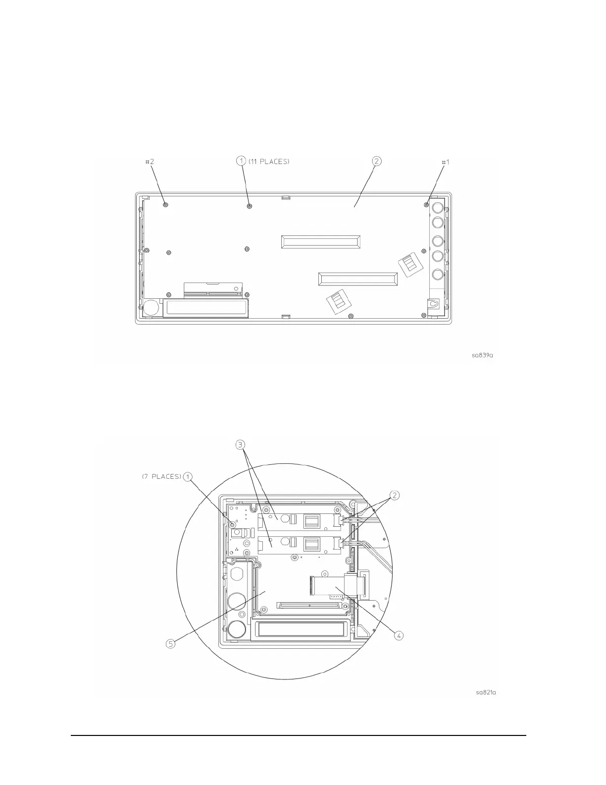
1. Refer to Figure 7. Using the T-10 driver, remove the 11 screws (1) securing the shield (2) to the
front frame. Lift the shield from the front frame.
Figure 7 Front Frame Shield Removal
2. Remove the front panel knob (RPG knob) by pulling it straight off of the control shaft.
3. Refer to Figure 8. Disconnect both of the 2-wire backlight cables (2) from the inverter boards
(3).
Figure 8 Front Panel Interface Board Removal

 Loading...


