16
www.agilent.com/find/esg
Mirror spectrum
Enabling the mirror spectrum feature inverts the Q channel, resulting in a mirrored
spectrum. As a signal normally propagates through the different functional blocks of a
receiver, for example the mixer block, the signal spectrum may be reversed. Using this
feature facilitates realistic testing of receiver functional blocks that would normally be
presented with a mirrored spectrum signal.
Clock and gate signals
The Signal Studio software makes use of the ESG markers to generate clock and gate
signals along with the configured waveform. These signals are necessary to perform BER
analysis on Bluetooth packets and data streams using the ESG internal BER analyzer.
A symbol clock is generated on the ESG event one port for all waveforms created using
the Signal Studio for Bluetooth software. Because Bluetooth is 2-level FSK modulated
(1 bit/symbol), the symbol clock can be used to indicate the bit rate of the incoming
data sequence to the ESG internal BER analyzer. When operating in packet generator
mode, a payload data gate signal is also provided on the ESG event two port. This gate
signal is used to recover continuous PN9 payload data from an incoming Bluetooth
packet sequence for BER analysis. Refer to the Basic measurements section for a
detailed example of how these signals are used to perform BER analysis.
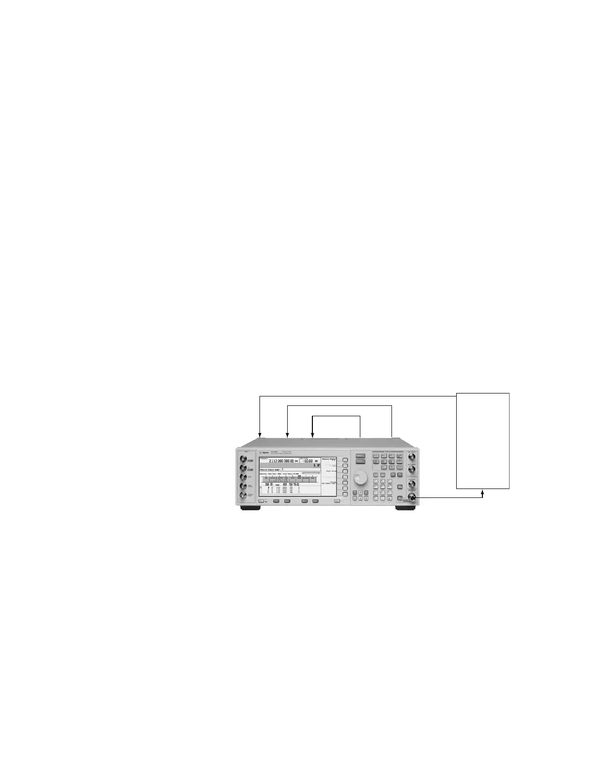
Clock/gate delay
When clock and gate signals generated by the ESG are used to perform BER analysis, it is
important to realize that the test signal transmitted by the ESG experiences a propagation
delay through the device under test. As a result, the demodulated loopback signal must
be realigned in time with the clock and gate signals at the input of the BER analyzer,
Figure 18. Delay control over the clock and gate signals is provided by the software to
enable realignment with the test signal at the input of the BER analyzer.
Figure 18. To perform BER analysis using this measurement setup, the clock/gate delay setting
(∆) must be equal to the propagation delay the test signal experiences through the Bluetooth
device (a).
If the propagation delay characteristics for the device under test are known, enter the
delay value in the clock/gate delay field during waveform configuration. The clock and
gate signals associated with the waveform will be delayed by the indicated amount during
waveform playback. The resolution of the clock/gate delay parameter is directly coupled
to the oversampling ratio setting. It can be determined by dividing the symbol period
(1 µs) by the oversampling ratio. To increase the incremental delay resolution, increase
the oversampling ratio of the configured waveform. When doing so, remember that
increasing the oversampling ratio also increases the projected length of the waveform.
Creating Signals
E4438C ESG vector signal generator
• Option 602 Baseband generator with 64 MSa
• Option 406 Signal Studio for Bluetooth
• Option UN7 Internal BER analyzer
BER
gate in
Event 2BER
data in
BER
clock in
Event 1
Delay = (t + a)
Delay = (t + ∆)
Delay = (t + ∆)
Bluetooth
DUT
Propagation
delay = a
RF test signal
Demodulated test signal
Rear panel

 Loading...


