17
www.agilent.com/find/esg
Clock/gate delay calibration
If the delay parameter is unknown, leave the default value (0 µs) in the clock/gate delay
field and finish configuring the waveform. After the waveform has been calculated, the
clock/gate delay calibration utility can be used to determine the delay characteristics of
the device under test.
Figure 19. Signal Generation Setup menu.
After the waveform has been downloaded to the ESG, select the calibrate button in the
Signal Generation Setup menu, Figure 19, to bring up the clock/gate delay calibration
utility, Figure 20. Once configured, the calibration utility generates a plot of BER versus
clock/gate delay. From the plot, the correct clock gate delay setting to realign the
signals at the input of the BER analyzer can be determined.
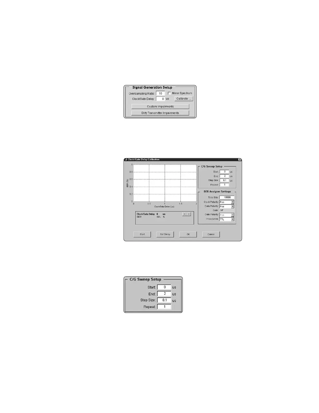
Figure 20. Clock/Gate Delay Calibration utility.
The Clock/Gate Sweep Setup menu is used to configure the calibration utility, Figure 21.
Enter the Clock/Gate Delay range in the Start and End fields. Typical propagation delay
through a Bluetooth device ranges from one to 10 µs; however, depending on the test
setup, longer delays are possible.
Figure 21. Clock/Gate Sweep Setup menu.
Creating Signals

 Loading...


