16
Theory of Operation
Temperature Controlled Autosampler Board (TCA)
multiplexer. The output of the multiplexer is connected to the autosampler
main board via the 26 pin autosampler to ALS thermostat cable. The
autosampler firmware checks the signals for correctness and initiates all
needed activities.
EPROM
The EPROM stores all relevant data for the ALS Thermostat (e.g., serial
number, board revision, etc.). This data are pre-set at the factory.
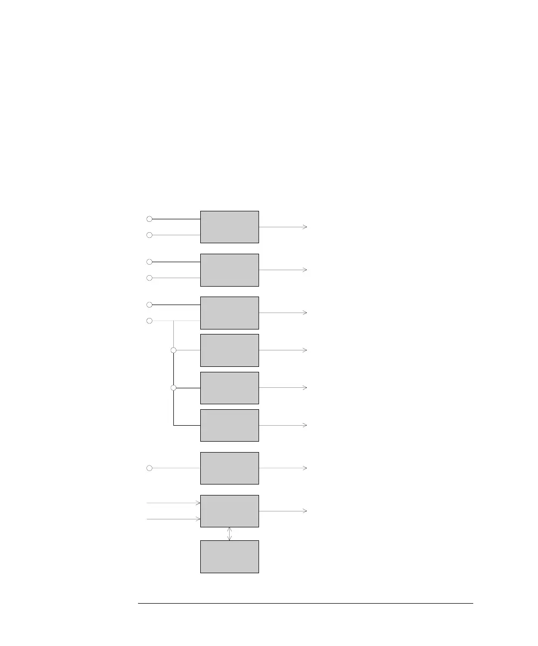
Figure 4 Block Diagram TCA Board
Step Down
Switcher 1
Step Down
Switcher 1
EPROM
Multiplexer
Auto Range
Regulator 3
Regulator 2
Regulator 1
Step Down
Switcher3
PDC 1
+ 36 V
PDC 2
PDC 3
+ 24 V
+ 36 V
Temp. Sensor 1 to 4
Fan Sensor 1 to 5
to ASM Board
Primary Board
Fan 5
Fan 3 + 4
Fan 1 + 2
Peltier Assembly C + D
Peltier Assembly B
Peltier Assembly A
+ 36 V
 Loading...