Installing the flow manifold
8
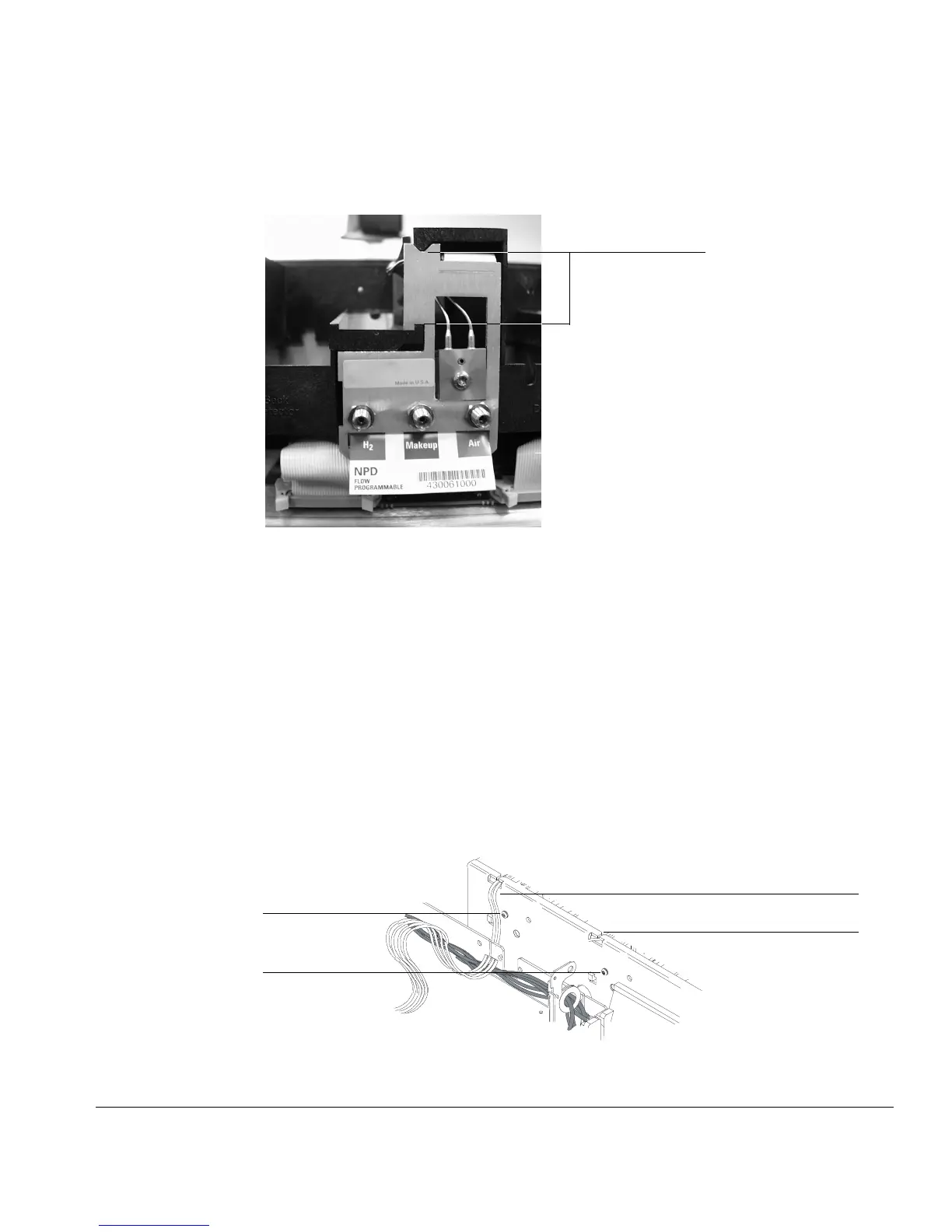
Figure 2. Manifold, after installation
2. Route the gas tubing behind the manifold, over the top of the chassis,
and through the slots.
3. Connect the ribbon cable to the mating connector on the pneumatics
board. Arrange the cable to keep it away from the valves and keep it
from being pinched against the manifold.
For the back detector, you may want to loosen the manifold and slide it
out of the carrier a few centimeters to connect the cable to the
pneumatics board. Then, reinstall the manifold.
4. From the front, secure the manifold to the chassis using the Torx T-20
screw.
Figure 3. Captive screws and tubing
Bracket is flush
with carrier rails
Front
captive screw
Back
captive screw
Front detector tubing
Slot for rear detector tubing