Do you have a question about the Agilent Technologies 1200 Infinity Series and is the answer not in the manual?
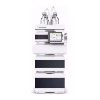
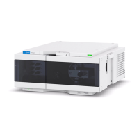
Provides a general overview of the Agilent 1200 Infinity Series DAD detector, detailing key features and capabilities.
Details the components of the detector's optical system, including the lamp, mirrors, flow cell, grating, and diode array.
Describes the Max-Light Cartridge Flow Cells available for the detector, their specifications, and optical principles.
Outlines the necessary environmental conditions and bench space requirements for optimal detector performance.
Lists the physical dimensions, weight, power consumption, and operating conditions of the detector.
Details the key performance parameters of the Agilent 1200 Infinity Series DAD, including noise, drift, and accuracy.
Provides instructions for safely unpacking the detector module, including handling potential damage and condensation.
Explains how to configure modules in a stack for optimal system performance and minimum delay volume.
Guides the user through the process of physically installing the detector module into the LC system.
Details the procedure for connecting the flow cell and tubing to the detector module.
Provides essential steps for preparing the detector before use, including warm-up and environmental considerations.
Explains how to configure and set up the detector using the Agilent ChemStation software.
Describes the graphical user interface of the detector, including its active areas and status indicators.
Details the available control settings for lamps, analog output range, and UV lamp tag usage.
Explains how to access and configure method parameters for the detector via menu or GUI.
Provides recommendations and guidelines for the use of various solvents with the detector's flow cell.
Provides a summary of parameters affecting detector performance and optimization strategies.
Guides users on selecting the appropriate Max-Light Cartridge Flow Cell based on application needs.
Details how to optimize detector performance by adjusting flow cell path length, peak width, and slit width.
Explains techniques for optimizing selectivity, including peak suppression and ratio qualifiers.
Explains the module's status indicators, error messages, test functions, and diagnostic signals.
Describes the two status indicators on the module and their meaning for operational states.
Details how error messages are displayed and propagated within the LC system.
Discusses the use of Agilent Lab Advisor software for diagnostic capabilities and maintenance routines.
Addresses common intermittent problems, such as loose optical cables, and their potential causes.
Provides guidance on resolving issues when the detector's main board type is incorrectly recognized.
Explains the meaning of error messages and their impact on analysis continuity.
Lists and describes generic error messages applicable to Agilent HPLC modules.
Details specific error messages related to the detector's components and functions.
Describes the self-test procedure, which runs a series of individual tests to evaluate detector performance.
Explains how to measure the intensity of the UV lamp across the full wavelength range.
Details the procedure for testing the detector's flow cell and its light absorption characteristics.
Guides users through the process of calibrating the detector's wavelength accuracy.
Highlights critical safety warnings related to handling hazardous materials and electrical shock.
Provides a summary of routine maintenance procedures that can be performed without opening the main cover.
Step-by-step instructions for replacing the deuterium lamp in the detector.
Detailed procedure for replacing the Max-Light Cartridge Flow Cell.
Lists essential parts and materials required for performing maintenance on the detector.
Details available kits, such as the Accessory Kit and Inline Pressure Relief Valve Kit.
Provides a general overview and classification of cables used with Agilent LC modules.
Details the specifications and pin assignments for analog cables.
Describes the various remote cables and their connections for instrument control.
Explains the structure of the instrument firmware, including resident and main system components.
Details the various electrical connectors and interfaces on the detector module.
Provides a comprehensive overview of the interfaces available on Agilent 1200 Infinity Series modules.
Explains how to configure the detector using the rear-mounted 8-bit configuration switch.
Outlines the initial steps required to establish LAN communication with the detector.
Details the TCP/IP parameters and methods for configuring the detector's network interface.
Describes the selectable initialization modes for determining active TCP/IP parameters after power-on.
Explains the process of automatic network configuration using BootP.
Guides users on setting up the PC and Agilent ChemStation for detector communication.
Provides essential safety information, including symbols, warnings, and general precautions.
Details compliance with the WEEE Directive for product disposal.
Offers recommendations for the use of solvents and flow cell maintenance.
| Brand | Agilent Technologies |
|---|---|
| Model | 1200 Infinity Series |
| Category | Security Sensors |
| Language | English |