44 Agilent 1200 Infinity Series DAD User Manual
3 Installing the Module
Flow Connections to the Detector
Flow Connections to the Detector
For bio-inert modules use bio-inert parts only!
Parts required # Description
1System
1 Max-Light cartridge flow cell
1 Capillaries and tubing from Accessory Kit.
Sample degradation and contamination of the instrument
Metal parts in the flow path can interact with the bio-molecules in the sample leading
to sample degradation and contamination.
➔ For bio-inert applications, always use dedicated bio-inert parts, which can be
identified by the bio-inert symbol or other markers described in this manual.
➔ Do not mix bio-inert and non-inert modules or parts in a bio-inert system.
This procedure shows the detector outside of a system. In an Agilent 1260 Infinity Liquid
Chromatograph, the detector is located below a G1316 TCC on the bench. In an Agilent 1290
Infinity Liquid Chromatograph, the detector is located between a G1316 TCC (below) and the
Solvent Compartment (above). (See
“Optimizing the Stack Configuration”
on page 32.
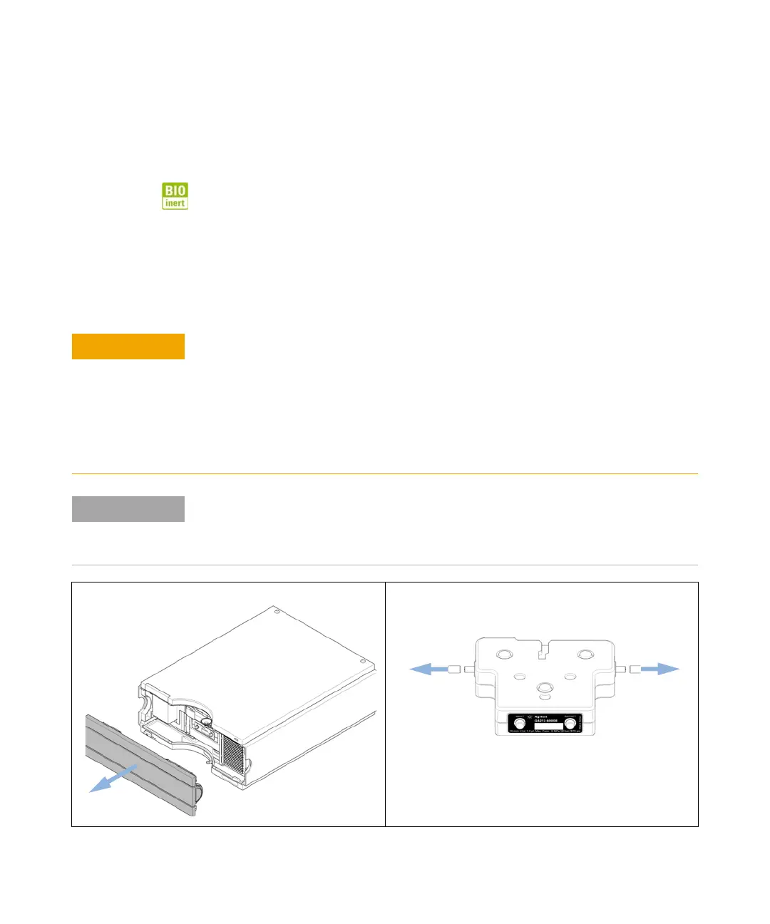
1 Remove the front cover. 2 Remove the black hoods from the cell interfaces (in/out)
and store them in the plastic case provided with the
Max-Light Cartridge Flow Cell.
 Loading...