Installation Note E8364-90024 19
Step 8. Reinstall the Test Port 1 Coupler and the Receiver Attenuator
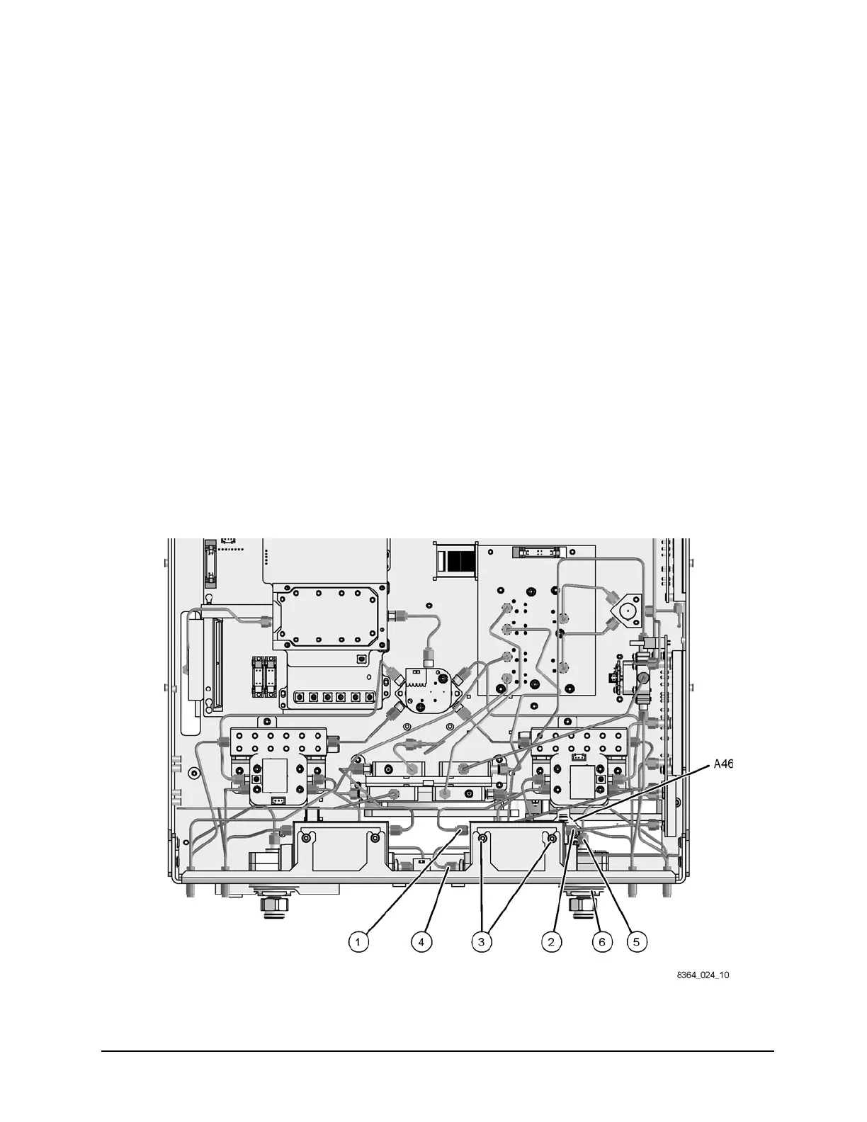
Refer to Figure 14 for this procedure.
1. Reinstall the A25 test port 1 coupler:
a. Place the test port coupler into position in the analyzer.
b. Using a 1-inch torque wrench reinstall the coupler nut (item
⑥).
c. Using a 5/16-inch torque wrench, reconnect the semirigid cable (item
④) to the coupler.
2. For analyzers with only hardware Options 014 and 080 combined, install the following new
cable (item
⑤):
• W67 E8364-20156 A25 test port 1 coupler to front panel PORT 1 CPLR ARM
3. Option 016 only. Reinstall the A43 channel A receiver attenuator:
a. Reconnect the ribbon cable to the attenuator and slide the attenuator into position in
the mounting tabs.
b. With a T-10 TORX driver, tighten the two mounting screws (item
③) to secure the
attenuator.
c. Using a 5/16-inch torque wrench, reconnect the semirigid cables (item
①) and (item ②).
Figure 14 Test Port Coupler and Receiver Attenuator Reinstallation
 Loading...


