Installation Note E8364-90024 21
Step 10. Reinstall the Front Panel Assembly and Front Panel Jumpers
CAUTION
Before installing the front panel assembly onto the analyzer, lift and support the
front of the analyzer chassis.
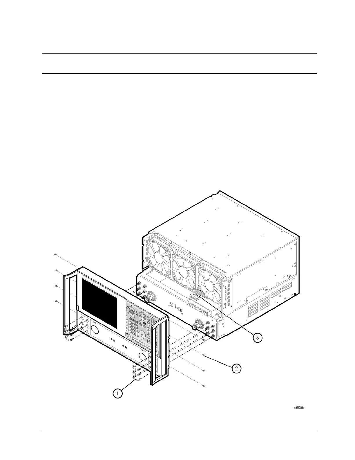
Refer to Figure 16 for this procedure.
1. Tighten all 12 of the front-panel feed-through connectors using a 5/16-inch torque wrench
set to 21-inch lbs.
2. Reconnect the ribbon cable (item
③
) to the A3 front panel interface board.
3. Slide the front panel over the test port connectors being careful to align the power switch
and floppy disk drive to their corresponding front panel cutouts. Ensure that the ribbon
cable (item
③
) is located below the fan to prevent it from being damaged by the fan blades.
4. With a T-10 TORX driver, install the eight screws (item
②
) in the sides of the frame.
5. Install the six semirigid jumpers (item
①
) on the front panel and tighten to 10-inch lbs.
Figure 16 Front Panel Assembly Reinstallation
 Loading...


