Chapter 1 29
Introduction
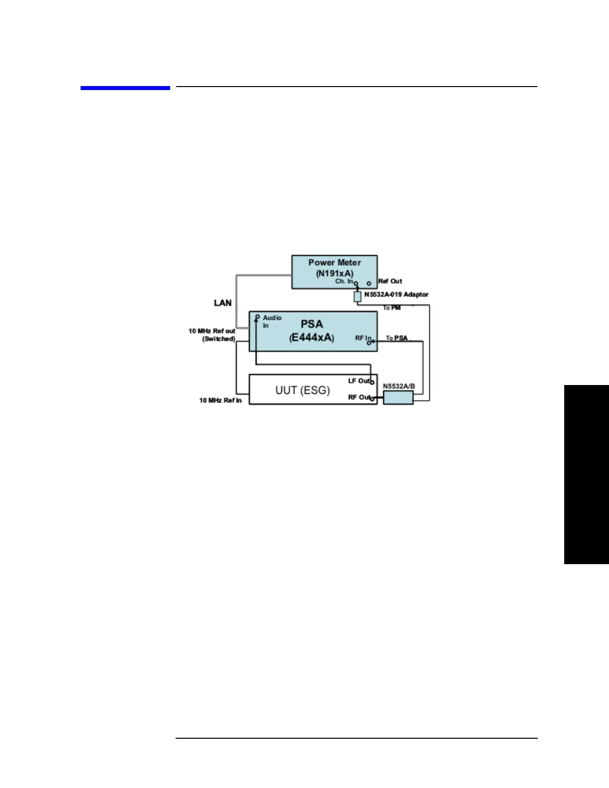
N5531S System Block Diagram
N5531S System Block Diagram
A block diagram of the N5531S Measuring Receiver System is shown below.
The system consists of:
1. PSA with Option 233 (refer to Table 2-1 on page 41.)
1. P-Series Power Meter (refer to Table 2-2 on page 41.)
1. N5532A/B Sensor Module (refer to Table 2-3 on page 42.)
Figure 1-2 N5531S System Block Diagram
The N5532A/B Sensor Module receives the incoming RF signal from the DUT and
splits it between the Power Meter and PSA. The RF Power and Absolute Tuned RF
Level measurements use the sensor module and power meter, whereas all other
measurements are performed using the PSA.

 Loading...


