37
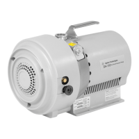
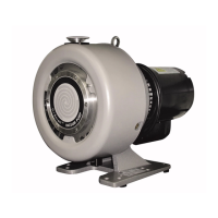
TriScroll 600 Series Vacuum Pump
DRA
FT 6/13/11
Three Phase Motor Connection
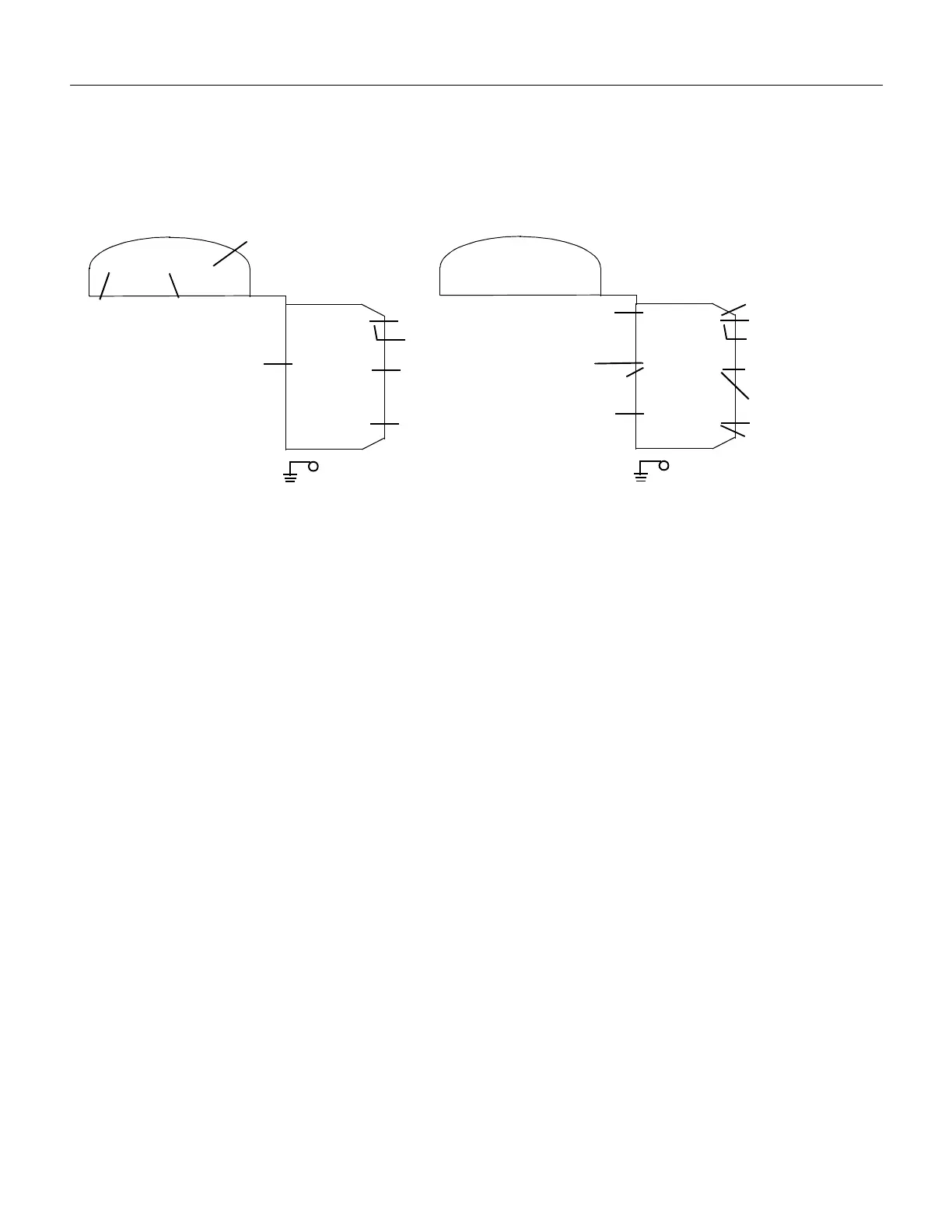
The pump can be configured for low voltage, 200 VAC to 230 VAC, or for high voltage, 380 VAC to 415 VAC and
460 VAC. As supplied from the factory, the pump is configured for low voltage. Figure 5 shows the electrical connections
for a three phase motor.
Figure 5 Three Phase Motor Electrical Connections
1. Verify the electrical supply voltage.
2. Remove the three screws (item 12 in Figure 3 on
page 35) that are holding the motor electrical cover
(item 13 in Figure 3).
3. Refer to Figure 5 to connect the motor to match your
supply voltage.
Two options are available to strain relieve the electrical
supply cable.
❑
The cable can be mechanically held under the
electrical cover in the groove provided. The
groove is sized for 14 gage cable.
❑
A 1/2
−
14 NPSM hole is also provided next to the
motor cover.
4. L1, L2, and L3 are the power cord leads.
Wire L1, L2 and L3 per Figure 5 using right angle flag
connectors or ring connectors.
Ensure that no exposed wiring is close to the electri-
cal cover or to other terminals on the board.
5. Secure the ground wire under the ground screw using
a ring connector.
6. Install the motor electrical cover and secure it with
the three (3) screws removed in step 2.
7. Momentarily switch on the pump to verify proper
rotation.
With the inlet uncovered, a strong air flow should
come out of the pump exhaust. If there is no flow out
the exhaust, reverse any two of the leads (L1, L2 or
L3).
8. Repeat the test to verify correct rotation.
7 8 9
. . .
. . .
. . .
5
2
6
3
4
1
High Voltage
.
L1
VPI Valve (Optional)
VPI Valve (Optional)
L3
L2
RED (7)
ORG (5)
WHT (8)
YEL (6)
BLU (9)
7 8 9
. . .
. . .
. . .
5
2
6
3
4
1
Low Voltage
.
L1
VPI Valve (Optional)
L3
L2
WHT (8)
YEL (6)
RED (7)
BRN
BLU (9)
ORG (5)
VPI Valve (Optional)
 Loading...