39
TriScroll 600 Series Vacuum Pump
DRA
FT 6/13/11
Wiring
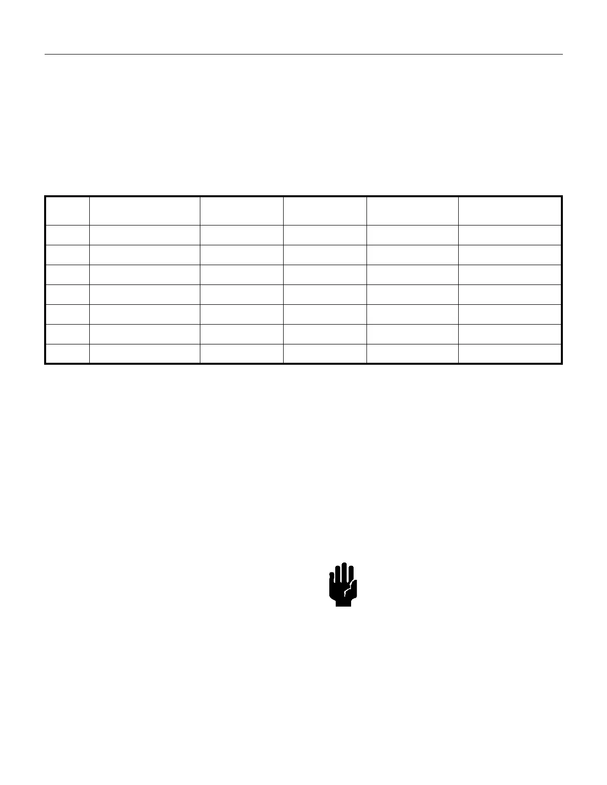
Using the data in Table 19, verify that the VPI Valve
chosen is compatible with the TriScroll supply voltage
and frequency. Then, locate the proper wiring diagram to
use (Figure 4 on page 36 or Figure 5 on page 37).
1. Remove the three screws (item 12 in Figure 3 on
page 35) that are holding the motor electrical cover
(item 13 in Figure 3).
2. Connect the VPI Valve solenoid wire leads to the
pump motor as shown in Figure 4 or Figure 5.
3. Replace the motor electrical cover and secure it using
the three screws removed in step 1. Verify that the
valve is properly grounded before applying
electrical power.
.
*
Solenoid operating voltages are lower than the TriScroll vacuum pump operating voltages in order to utilize the TriScroll motor’s inter-
nal thermal switch to actuate the VPI Valve.
Gas Ballast
The pump incorporates an automatic gas ballast to
prevent water and other condensates from accumulating
within the pump. The standard configuration is a sintered
filter installed in the 1/4" National Pipe Thread gas ballast
port (item 9 on Figure 3 on page 35). This allows enough
atmospheric air to enter the pump in order to purge
condensates while not affecting pump ultimate pressure
or pumping speed.
For applications where the ingress of atmospheric air is
undesirable, dry nitrogen at a flow rate of
≈
5 lpm can be
bled into the gas ballast port. See “Purge Kit” below.
Blocking of the gas ballast port is not recommended.
Bearing Purge
A 1/4" National Pipe Thread bearing purge port (item 6 on
Figure 3 on page 35) protects the main crankshaft
bearings in applications where large amounts of water are
being pumped. In the standard configuration, this port is
sealed.
To enable the bearing purge, dry nitrogen at a flow rate of
≈
5 lpm can be bled into the bearing purge port. This gas
supply should be maintained at 2 psig or less and must be
kept below 5 psig. See “Purge Kit” below.
Purge Kit
A purge kit (Agilent part number PTSPURGEKIT) is
available to properly purge either the bearing purge or the
gas ballast. This kit contains a flowmeter and all
necessary valving and tubing.
Table 19 VPI Valve Installation Data
Motor TriScroll Vacuum Pump
Operating Voltage
VPI Valve Part #
NW25
VPI Valve Part #
NW40
Solenoid Operating
Voltage Range
Use the following
Wiring Diagram
1 Phase 100-120 V 50/60 Hz VPI251205060 VPI401205060 90-132 V Figure 4 low voltage
1 Phase 200-230 V 50/60 Hz VPI251205060 VPI401205060 90-132 V* Figure 4 high voltage
3 Phase 200 V 50/60 Hz VPI251205060 VPI401205060 90-132 V* Figure 5 low voltage
3 Phase 230 V 50/60 Hz VPI251335060 VPI401335060 120-146 V* Figure 5 low voltage
3 Phase 380 V 50/60 Hz VPI252205060 VPI402205060 180-264 V* Figure 5 high voltage
3 Phase 415 V 50/60 Hz VPI252205060 VPI402205060 180-264 V* Figure 5 high voltage
3 Phase 460 V 50/60 Hz VPI252665060 VPI402665060 239-293 V* Figure 5 high voltage
CAUTION The bearing purge port has been
disabled on the TriScroll 600
model S4800309. Use of this port
could cause internal damage to
the pump.
 Loading...