2.1. Electrical Interface Introduction
2.1.1 Robotic Arm Electrical Panel Instructions
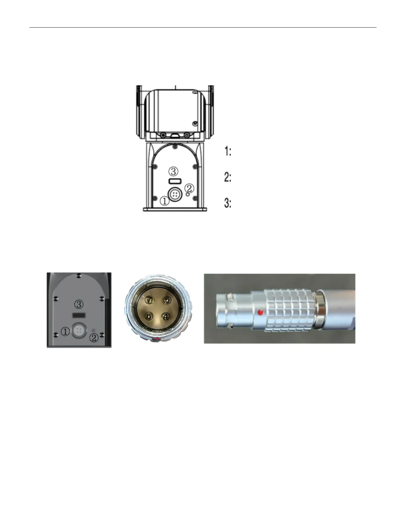
2.1.2 Aviation plug Instructions
1: Power and communication port
2: Status indicator light
3: J1J2 connection port
4: Power positive
5: Power negative
6: CAN-H
7: CAN-L
Note: Align the red dot with the corresponding red dot on the cable. The textured area of the connector is designed to retract
under force. During installation, align the red dot downward with the protruding point and insert it directly. To remove, press down
on the textured area and pull it out.