1. If the light is off, click the button once. The green light should turn solid, indicating that the user can drag the robotic arm to
start recording the trajectory.
2. If the light is off and a trajectory has been recorded previously, double-click the button. The green light should flash every 500ms,
indicating the robotic arm is in playback mode and will reproduce the recorded trajectory.
3. If the light is solid, it indicates trajectory recording is in progress. To stop the recording, click the button once; the light should
turn off, indicating that recording has ended. If you want to replay the trajectory, follow step 2.
4. If the light is flashing, the robotic arm is currently in playback mode.
Notes:
1. During trajectory playback, the user must keep a safe distance from the robotic arm to avoid injury.
2. Each time the robotic arm enters teach trajectory recording mode, the previously recorded trajectory is erased. The playback
mode will use the most recent recorded trajectory.
3. The maximum trajectory recording time is 3 minutes; any trajectory exceeding this time will be invalid.
4. After finishing drag teaching, ensure the indicator light is off/drag teaching mode is stopped.
5. If you want to switch to host computer control or command control, ensure the indicator light is off/drag teach mode is stopped.
Then switch to standby mode via the host computer, and after entering standby mode, switch to CAN mode. The same applies to
command control—first switch to standby mode, then switch to CAN control mode.
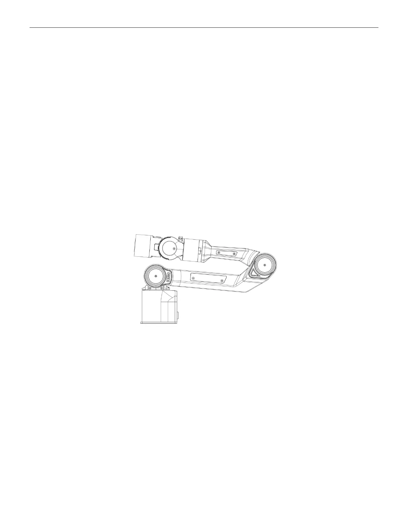
Note: When switching from link mode and teach by dragging mode to CAN control mode, the robotic arm must be positioned at the
zero point before changing modes. The zero point is shown in the figure below:
Robotic Arm Zero Point
2.3. Base Installation Instructions
The robotic arm base is installed using screws for fixation. The base has four pre-drilled M5 threaded holes. The accessory kit
includes four M5 screws, which can be tightened using the provided hex tool. The hole spacing is 70mm. If you need to attach the
base to mobile equipment or a fixed surface, you can design the corresponding structure with 70mm hole spacing.