5 | Control and display elements AHT Cooling Systems GmbH | en
34 / 505 405859_1_0819
NOTICE
Property damage caused by making incorrect
changes to the operating element parameters.
▪ After operating, reattach the Plexiglas cover.
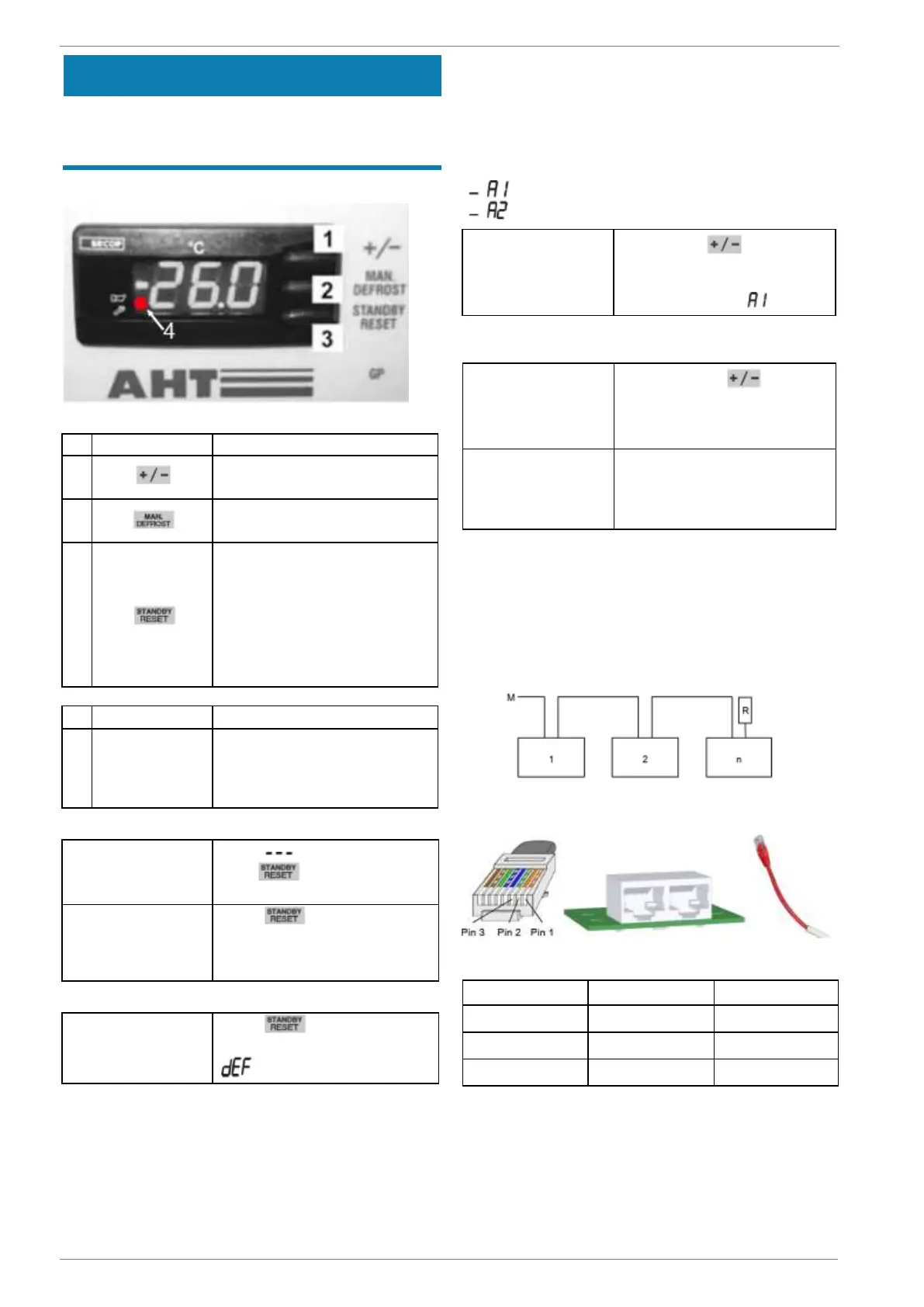
The following keys are available as operating elements:
Fig. 1: Operating elements and display indicators
–
Application change
–
Raise bus address
–
Start semi-automatic
defrosting
–
Start defrosting manu-
ally
–
Switch the cooling func-
tion on and off
–
Call error code (if red
dot illuminated)
–
Acknowledge acoustic
alarm
Illuminated red
dot (next to the
klaxon symbol)
5.2.1 Cooling function
Switch off cooling
function (start de-
frosting manually)
Press for at least 3 sec-
onds. appears on the
display.
Switch on the cool-
ing function
Press for at least 3 sec-
onds.
The interior temperature ap-
pears on the display.
5.2.2 Semi-automatic defrosting
Start semi-automatic
defrosting
Press for at least 3 sec-
onds.
appears on the display.
Defrost time
–
Up to 99 min.
After semi-automatic defrosting, the appliance automat-
ically returns to normal operation.
The current interior temperature appears on the dis-
play.
24-hour defrost block
The 24-hour defrost block is active if briefly appears
on the display, followed by the interior temperature.
5.2.3 Application
The following applications can be selected (customer-
specific release):
If no change is required, the display returns to the
temperature display after approx. 5 seconds.
By pressing the button
several times, you can run
through all applications re-
leased.
The applications newly set will
be set automatically approx. 5
seconds after pressing the the
button for the last time.
5.2.4 Bus address
Before assigning the bus addresses, the appliances
(1, 2,...n) must be networked with an appropriate bus
cable.
The first appliance (1) must be connected to market
monitoring (M) via the bus cable.
The bus cable must be terminated with a terminating
resistor (R) on the last device (n).
Fig. 2: Bus system diagram
For technical data, see → Technical data
Fig. 3: RJ45 connector bus cable, RJ45 sockets device and
terminating resistor (R)
The controllers are supplied as standard with bus ad-
dress “1” (corresponds to a stand-alone appliance).
To identify several appliances in the bus system, the
bus addresses must be assigned starting with “1”.
Display selected ap-
plication
Briefly press .
The currently selected
application appears
on the display, e.g.
 Loading...