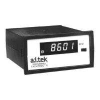
The AI-TEK Instruments TACHTROL® 3 is an applications-oriented, single or dual-channel computing tachometer designed for measuring the rate of industrial events. It utilizes the period mode of frequency measurement (time per event) to provide accurate readings.
Function Description:
As a single-channel tachometer, the TACHTROL® 3 measures the rate of various industrial events. This could include the rate at which liquid flows through a pump, or the speed at which bottles move along a conveyor belt. The device then displays these rates in user-defined engineering units such as Feet Per Second (FPS), Gallons Per Hour (GPH), Revolutions Per Minute (RPM), and other relevant units.
In its dual-channel configuration, the TACHTROL® 3 can simultaneously read two unrelated speeds. Alternatively, when two speeds are related, it can compute six different mathematical functions from their input signal frequencies. These functions include:
- A - B (Difference): Calculates the difference between Speed A and Speed B.
- A - B x 100 / A (% Slip): Determines the percentage of slip between two speeds.
- A / B (Ratio): Computes the ratio of Speed A to Speed B.
- B / A (Inverse Ratio): Computes the inverse ratio of Speed B to Speed A.
- B - A x 100 / A (% Elongation): Calculates the percentage of elongation.
- (A + B) / 2 (Average): Determines the average of Speed A and Speed B.
Additionally, the TACHTROL® 3 can function as a bi-directional tachometer. When used with an AI-TEK bi-directional sensor, it measures speed and indicates the direction of movement (+A or -A for opposite direction).
The tachometer's microcomputer allows for flexible scaling of input signal frequencies to achieve appropriate display values. Users can select and route mathematical functions to various outputs and define the behavior of each output.
Usage Features:
The TACHTROL® 3 offers a range of features to customize its operation and output behavior:
- Display: An LED display updates every 0.5 seconds, showing the computed function. The display has 4 1/2 digits, with the leftmost digit being a 1/2 digit (showing only a blank or a one). Any two-channel calculation can result in a negative quantity. Values too large for the display will cause it to flash its largest value (19999).
- Autoranging: The display supports autoranging, allowing the decimal point to move among the 4 1/2 digits. Users can limit this movement to determine the smallest value the display will show.
- Analog Output: An optional current source provides either a 4 to 20mA or 0 to 20mA output. The zero scale and full scale of the analog output can be determined by setting specific values of the analog function. The 0-20mA output can be converted to a 0 to 5vdc or 0 to 10vdc signal by adding a resistor across the input of the receiving instrument.
- Relay Setpoints: The device includes 1 or 2 optional relay setpoints (2 form C contacts) that can trigger external events, such as alarms. These setpoints can be configured as either underspeed or overspeed.
- Underspeed Setpoints: Trigger events when the frequency drops below the setpoint.
- Overspeed Setpoints: Trigger events when the frequency rises above the setpoint.
- Setpoint Behavior: Relays can be configured to energize or de-energize above or below the setpoint value. Non-Failsafe relays energize above the setpoint (overspeed) or below the setpoint (underspeed). Failsafe relays de-energize above the setpoint (overspeed) or below the setpoint (underspeed), providing a warning in case of power failure while the machine is operating in the non-alarm (safe) area.
- Latching/Auto Reset: Relays can be set to Latching or Auto Reset. Latching relays remain in an alarm condition until manually reset via a pushbutton. Failsafe Auto Reset relays automatically energize when the machine returns to its non-alarm state. Relays can also be programmed to reset at the setpoint or with a Hysteresis (dead band) to prevent "chatter" as frequency hovers around the setpoint value. Hysteresis is specified as a percentage of the setpoint value, with its position (above or below the setpoint) determined by the relay type.
- Input Options: The instrument can be programmed for different sensor types (TTL or AC signals from passive magnetic sensors) using dip switches. For TTL inputs, the negative input on the terminal block must be connected to the common terminal.
- Time Mode Operation: The TACHTROL® 3 can display the time between pulses in microseconds by setting the denominator of each scaling factor to zero. This allows for time-based measurements to be used with all functions and outputs.
Maintenance Features:
- Constant Storage: All configured constants are retained in the electrically alterable, read-only memory (EAROM) and can be altered multiple times.
- Control Panel Access: The control panel, located behind a door on the display, provides access to thumbwheel and pushbutton switches for setting up the instrument.
- Viewing Constants: Constants can be individually displayed and altered. By setting the Constant Thumbwheel (CTW) to a number other than "0", the instrument stops operating as a rate monitor, outputs freeze, and the display shows the selected constant. After reviewing, returning the CTW and Digit Thumbwheel (DTW) to zero and pushing the pushbutton (Pb) returns the instrument to normal operation.
- Decimal Location: The Digit Thumbwheel (DTW) and pushbutton (Pb) are used to locate the decimal point when the DTW is set to "0".
- Digit Alteration: When the DTW is set to a display digit, pushing and holding the Pb changes the number in that digit.
- Factory Settings: The A.O. Full Scale R31 is factory set and typically does not require calibration. However, it can be adjusted by inputting signals that force the output beyond the analog output full scale and then adjusting R31 to 20 milliamps using an accurate current meter.
- Troubleshooting: The manual provides guidelines for installation and wiring practices to avoid common issues, particularly those related to electrical noise. It suggests reducing electrical noise at the source by installing snubber networks or commercially available noise suppressors across relay contacts, relay coils, and buzzers.
- Repair Policy: Attempts to repair the TACHTROL® 3 in the field are not recommended. Users are advised to contact Deca Systems, Inc. if a problem occurs.