7.0 APPENDIX: TIME MODE OPERATION
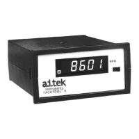
The TACHTROL
®
3 tachometer can be configured to display the time between pulses in micro
seconds by setting the denominator of each scaling factor (C2 and C4) to zero. The scaled input fre-
quency is now as follows:
C1
A = OR C1 = A x 10
-6
x fA
fA x 10
-6
C3
B = OR C3 = B x 10
-6
x fB
fB x 10
-6
Example:
C1 = 1.000
C2 = 0.000
fA = 2000hz
1.000
A = 2000 x l0
6
= 500
The resulting number in micro seconds can be used with all the functions and outputs in the
TACHTROL
®
3 tachometer.
SPECIFICATIONS
INPUT SIGNAL:
Frequency: 2 Hz to 30K Hz
Passive Pickup (Sine wave): 200 mV to 25 VRMS standard, 2K ohm impedance, common mode
rejection: 40 db, balanced input, sensitivity measured at I KHz.
Active Pickup (TTL): duty cycle 20 to 80%; DC pickup power, 12 VDC @ 100 mA (will power two (2)
zero velocity pickups or one (1) bi-directional pickup).
Bi-Directlonal Pickup: One (1) frequency input (TTL input A) and the direction input (TTL input B) from
a Bi-Directional pickup. (High (+5v) indicates positive direction, and only single speed functions
(Speed A) are useful when connected in this operation mode.
POWER SUPPLY:
120 VAC± 10%. 50-60 Hz.
24 VDC (23-30 VDC), standard (750 ohm analog load)
(20-30 VDC with 600 ohm analog output load)
240 VAC± 10% 50-60 Hz.
15 watts maximum
TEMPERATURE:
Operating: 0 to 50° C (ambient)
Storage: -40° to + 80° C
HUMIDITY:
90% relative and non-condensing
VIBRATION:
Designed to meet MIL 810C. method 514.2. Procedure VIII, Fig. 514.2-6, curve V (l.5g’s 10-200 Hz)
SHOCK:
Designed to meet MIL 810C, method 516.2. Procedure 1. Fig. 516.2-2 for ground equipment (30g’s
half sine)
23

 Loading...