3.0 THEORY OF OPERATION
Speed sensors (transducers such as AI-Tek series 70085, H or BH) are placed near ferrous metal tar-
gets such as gears. The sensors generate repeating electrical pulses (input signal frequencies) whose
repetition rates are proportional to the rates of the event. The TACHTROL
®
3 tachometer measures
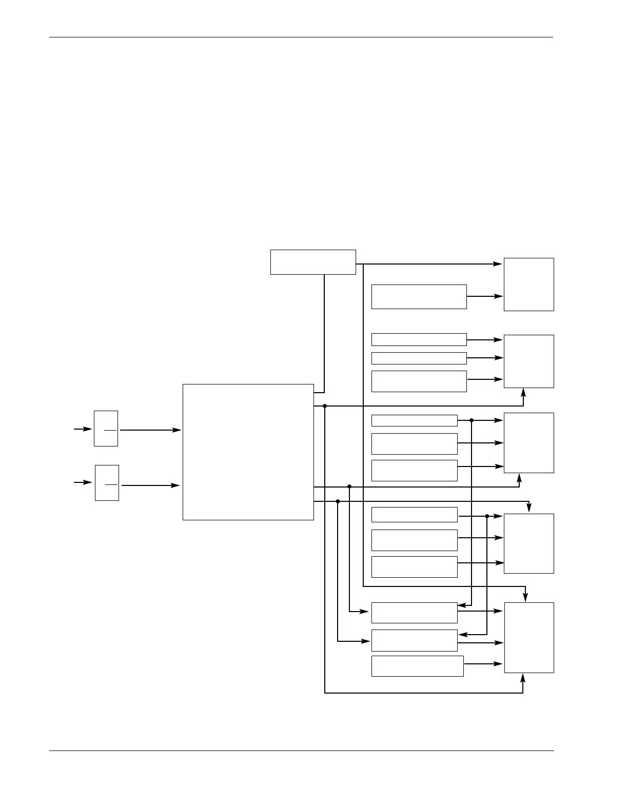
these rates in the number of pulses per second. The tachometer’s microcomputer allows you to scale
the input signal frequencies to appropriate display values, select and route the mathematical
functions to the outputs, and define the behavior of each output. Figure 1 illustrates the flow of data
in the TACHTROL
®
3 tachometer.
Figure 1, Data Flow Diagram
2
C5 - ADDITIONAL
SCALING FACTOR
C12-DIGIT 1
DECIMAL LOCATION
C6-ZERO SCALE
C7-FULL SCALE
C12-DIGIT 5
0-20 / 4-20 mA
C8-SETPOINT
C10-DIGITS 1 & 2
% HYSTERESIS
C12-DIGIT 2
RELAY LOGIC
C9-SETPOINT
C10-DIGITS 3 & 4
% HYSTERESIS
C12-DIGIT 3
RELAY LOGIC
FUNC. K1 S.P.
= DEVIATION
FUNC. K2 S.P.
= DEVIATION
C12-DIGIT 4
SER. OUTPUT INFO
DIGIT 1
FUNCTION C11
DIGIT 2
0=OFF
1 = A
2 = B
3 = A-B
4 = +/- A
5 = A/B
6 = B/A
7 = (A+B) / 2 DIGIT 3
8 = (A+B) / Ax100
DIGIT 4
9 = (B-A) / Ax100
C
1
X
C2
F
A
F
B
C
3
X
C4
ANALOG
DISPLAY
SET-
POINT 1
SET-
POINT 2
SERIAL
OUTPUT
A RESULT
B RESULT
 Loading...