6.0 HOW TO INSTALL THE SPEED SENSOR
6.1 MOUNTING THE SPEED SENSOR:
In most applications, Passive (not powered) speed sensors will be used. Low speed applications
(typically below 100 RPM) will require an Active (powered) or Zero Velocity speed sensor.
The mounting for both types of sensors should be able to accommodate several threads and
heavy enough to prevent excessive vibration. The mounting material should be non-magnetic.
The normal vibration of the machine in operation will not affect the accuracy of the display
reading. However, relative motion between the sensor and the gear can cause incorrect
readings.
6.2 SETTING THE CLEARANCE:
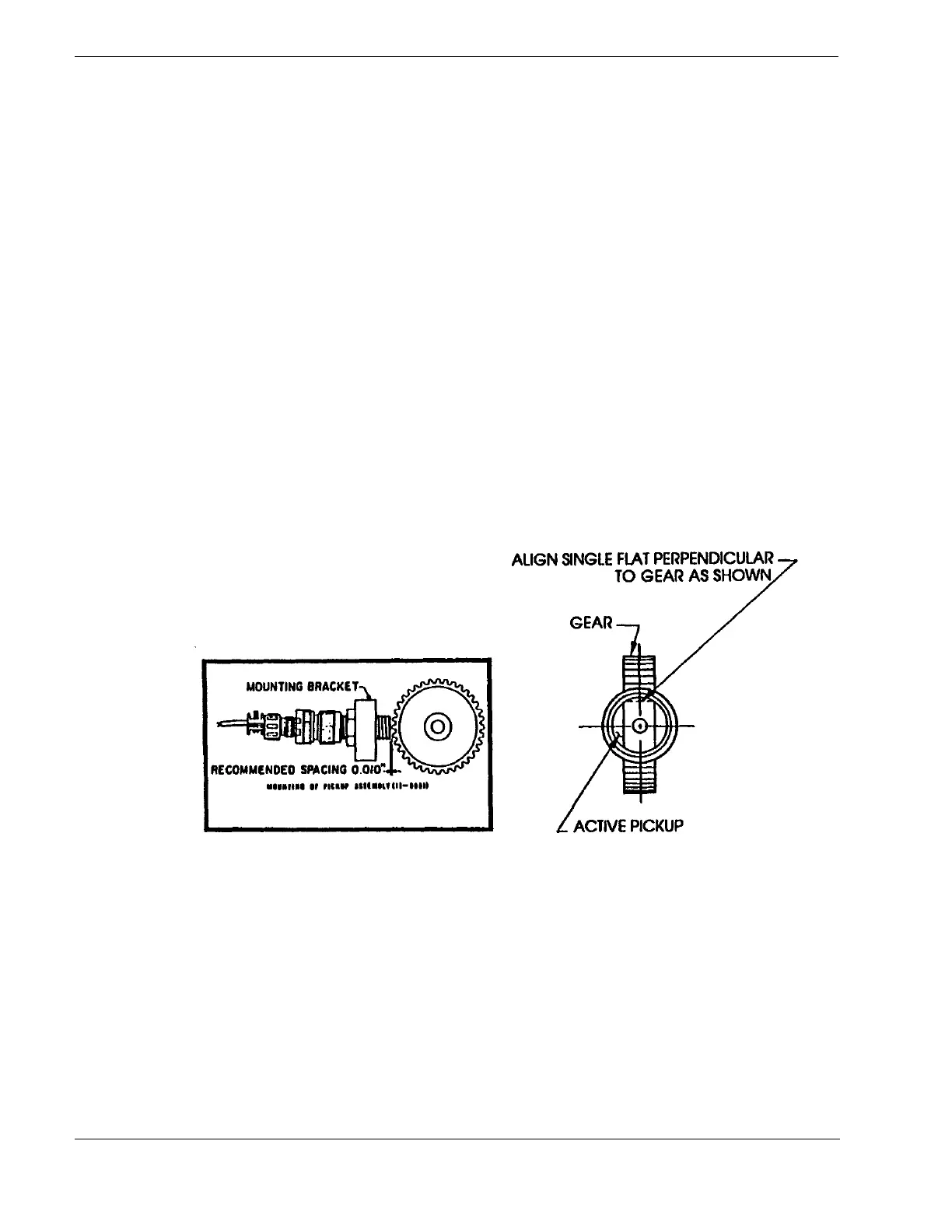
If you are using an AI-Tek Speed Sensor, use a feeler gauge to set the clearance. For Passive
Sensors a clearance of .005 to.030 inches is recommended. For Active Sensors a clearance of
.010 to .060 inches is recommended. Increasing the clearance beyond these values causes the
amplitude of Passive Sensors to decrease and may cause Active Sensors to cease operation.
CAUTION: AT NO TIME IN ITS REVOLUTION SHOULD THE GEAR TOUCH THE SENSOR OR DAMAGE
MAY OCCUR. When you have set the clearance, check the setting to see that a complete
revolution of the gear does not in any way contact the sensor.
Proper orientation of Active Sensors is also required. Flats on the housing must be in the same
plane as the gear. See diagram below:
If you are using another manufacturer’s speed sensor, consult the manufacturer’s recommended
installation procedures.
6.3 TYPICAL WIRING CONNECTIONS FOR AI-TEK SENSORS
Signal leads between the sensors and the instrument should be shielded, twisted pairs with
insulation over the shielding. This will provide effective noise shielding and is recommended for
all pickup, analog output, and serial data cables. Nevertheless, care should be taken to run
signal leads away from noise sources such as switching and power lines carrying large currents.
Shields should be connected at the TACHTROL
®
3 end only. The shields at the sensor end should
be trimmed and taped so there is no contact with the conduit or other grounds. Make sure you
connect terminal 11 to an earth ground.
20
 Loading...